These are the ramblings of Matthijs Kooijman, concerning the software he hacks on, hobbies he has and occasionally his personal life.
Most content on this site is licensed under the WTFPL, version 2 (details).
Questions? Praise? Blame? Feel free to contact me.
My old blog (pre-2006) is also still available.
See also my Mastodon page.
- Raspberry pi powerdown and powerup button (45)
- Repurposing the "Ecobutton" to skip spotify songs using Linux udev/hwdb key remapping (3)
- How to resize a cached LVM volume (with less work) (2)
- Reliable long-distance Arduino communication: RS485 & MODBUS? (6)
- USB, Thunderbolt, Displayport & docks (21)
| Sun | Mon | Tue | Wed | Thu | Fri | Sat |
|---|---|---|---|---|---|---|
| 1 | 2 | 3 | 4 | 5 | 6 | |
| 7 | 8 | 9 | 10 | 11 | 12 | 13 |
| 14 | 15 | 16 | 17 | 18 | 19 | 20 |
| 21 | 22 | 23 | 24 | 25 | 26 | 27 |
| 28 | 29 | 30 |
(...), Arduino, AVR, BaRef, Blosxom, Book, Busy, C++, Charity, Debian, Electronics, Examination, Firefox, Flash, Framework, FreeBSD, Gnome, Hardware, Inter-Actief, IRC, JTAG, LARP, Layout, Linux, Madness, Mail, Math, MS-1013, Mutt, Nerd, Notebook, Optimization, Personal, Plugins, Protocol, QEMU, Random, Rant, Repair, S270, Sailing, Samba, Sanquin, Script, Sleep, Software, SSH, Study, Supermicro, Symbols, Tika, Travel, Trivia, USB, Windows, Work, X201, Xanthe, XBee
 &
&
(With plugins: config, extensionless, hide, tagging, Markdown, macros, breadcrumbs, calendar, directorybrowse, feedback, flavourdir, include, interpolate_fancy, listplugins, menu, pagetype, preview, seemore, storynum, storytitle, writeback_recent, moreentries)
Valid XHTML 1.0 Strict & CSS
On my mailserver, I'm using Spamassassin with a Bayes filter to detect spam. Such a filter needs to be trained with samples of spam and ham (non-spam) messages to let it learn what spam and ham looks like, but it also needs to be retrained when the spam or ham changes over time. I have some automatic training set up, but since a while I've seen the bayes filter being completely wrong (showing a confident ham score for something that is very clearly spam), so I decided to retrain the filter from scratch, using the spam and ham messages I collected over the last time (I don't really throw away any e-mail).
Since training with all my e-mail is not productive (more than 5,000
messages aren't really helpful AFAIU, and training with old messages is
not representative for current messages), I decided to just take all of
my e-mail and take the last 2,000 spam and ham messages and train with
that. My spam is neatly collected in 2 mailboxes (Spam for obvious spam
and ProbablySpam for messages that need an occasional review to find
false positives), but my ham is sorted out in dozens of different
mailboxes. Hence, I needed some find magic to get a list of the most
recent spam and ham messages. So, I built these commands:
# find Spam ProbablySpam -type f \( -path '*/cur/*' -o -path '*/new/*' \) -printf "%T@ %p\n"
  | sort -n | cut -d' ' -f 2 | tail -n 2000 > spam
# find . -type d \( -path ./Spam -o -path ./ProbablySpam -o -path ./Bulk -o -path ./Sent \) -prune -o \
         -type f \( -path '*/cur/*' -o -path '*/new/*' \) -printf "%T@ %p\n" \
  | sort -n | cut -d' ' -f 2 | tail -n 2000 > ham
# sa-learn --progress --spam -f spam
# sa-learn --progress --ham -f ham
After retraining with recent spam, the results were a lot better, so I'm not longer spending time every day deleting a couple dozens spam e-mails :-D
XBee modules are a range of wireless modules built by Digi, and are typically used to add wireless connectivity to Arduino or other microcontroller based projects. To configure these modules and update their firmware, you can use the XCTU configuration utility. This utility uses a serial port to talk to the XBee module, so you will need some way to connect to the XBee module to a serial port on your computer (using a USB "TTL" serial port, a "real" RS232 port has too high voltage).
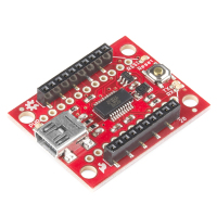
The easiest way is to use a dedicated board, like the SparkFun Explorer USB:
However, if you already have an Arduino and an XBee shield for it, you might want to use those to connect XCTU to your XBee module. In theory, this should be a matter of re-arranging some wires, but in practice I've run into some problems attempting this (depending on the hardware used).
In this post, I'll show a few ways to do this using an Arduino and a shield, and explain some of the problems you might run into.
First, let's see what connections we really need. When wiring things up using an XBee explorer, these are the connections made (leaving out stuff like the reset button, leds, and power and ground connections):
Here, the two data lines (TX/RX/DIN/DOUT) are the most important, those are needed for configuration and normal firmware updates. The other handshaking/flow control signals can prevent overflowing buffers at high speeds, but that is not normally a problem. They might also be needed to recover from a failed firmware upgrade, to force the XBee module into bootloader mode.
So, how can you use an Arduino and XBee shield to achieve these connections? Below, three variants are explored, each with different requirements, advantages and disadvantages.
Bypassing the Arduino microcontroller
Most Arduinos contain a single microcontroller (MCU), and have a
USB-to-serial converter integrated on the board as well. This
USB-to-serial converter is connected to the microcontroller, so it can
be used to upload programs to the Arduino, and send debug output using
Serial.println(). The connections on the Arduino Uno board are like this:
The resistors you see here are protection resistors, to prevent a short circuit when you connect another serial device to the Arduino's RX pin, but at the same time the USB-to-serial device also enables its TX pin. As you'll see later, these resistors might cause issues as well.
Now, to connect the XBee to XCTU, you can connect it to the USB-to-serial converter. To do so, you should connect the DOUT pin to the Arduino's TX pin, and the DIN pin to the Arduino's RX pin. This seems wrong, but remember that you want to talk to the USB-to-serial chip, not the Arduino. This would look like this (voltage converters not shown):
How to obtain this configuration depends on the shield used. The official Arduino Wireless SD shield, as well as some others, have a switch that can enable this wiring (in the other position, the connections are reversed, making the XBee module talk to the microcontroller instead). On some shields, like the SparkFun XBee shield, there is switch that can connect the the XBee module to pin 2 and 3 on the Arduino. Then, by connecting pin 0 to 3 and 1 to 2 on the shield's pin header, you get the above configuration. Yet other shields, like the one from ITEAD, simply have a long row of jumpers that allow connection DIN and DOUT to any I/O pin you want.
Interfering microcontroller
Note that the microcontroller is also still connected, since the Arduino board has no way to disconnect it. To prevent the microcontroller from interfering with the XBee communications, you will have to actually remove the microcontroller from the socket. This is not possible with all Arduino boards, though. If you do this, the auto-reset stuff below does not apply, though the pullup problems do.
You might think (I did) that you can also just upload an empty sketch to the Arduino, which keeps its serial port disabled. However, when XCTU opens up the serial port, the Arduino resets and the bootloader runs for a second or so, enabling the the serial port during that time. Because XCTU sends some data, the bootloader keeps running for longer, making the communication between XCTU and the XBee module fail.
Disabling auto-reset
This can be fixed by disabling auto-reset, but the only reliable way I've found to do this is to cut the "RESET EN" solder jumper. Since you'll have to re-solder the jumper again to enable it (needed for uploading new sketches), this seems a hassle. A lot of people online mention fiddling with a specific value resistor or capacitor to disable auto-reset, but that didn't work for me (I think the point is making the reset pulse so short it goes undetected, which is of course a bit shaky in any case). Connecting RESET directly to the 5V pin worked for me, but this creates a very brief short circuit whenever it would otherwise auto-reset (which might damage the usb-to-serial chip, though I'm not sure if this is a real risk).
Instead of disabling auto-reset, you could also try to keep the Arduino in reset by connecting RESET to GND. Again, this works, but has the same brief short circuit described above.
Problems with pullups
Even if you solve these problems, you might run into further problems, depending on the XBee shield used. Since Arduinos typically run at 5V and XBee modules at 3.3V, shields need voltage converters (which were hidden in the previous image). For example, the SparkFun XBee shield uses a transistor and two pullup resistors for this converter. This results in the following (only the DIN line is shown, DOUT is identical):
Since the pullups used are 1kΩ, just like the protection resistors in the Arduino board, communication will break. When the USB-to-serial converter pulls its TX line low, a resistor divider is created, resulting in 2.5V on the transistor instead of 0V, preventing it from switching on. A similar problem can occur when a resistor divider is used for voltage conversion, like the ITEAD shield does, though that particular shield uses big enough resistors (10kΩ) to not cause any problems.
So, this bypass approach is only limited in use. If you use it, you can do both configuration as well as firmware updates in XCTU. Recovering from a failed firmware upgrade is sometimes possible, but since no handshaking connections are available, this does not always work (in particular, it only works if the bootloader detects that the firmware update has failed, so the bootloader stays active all the time).
Forwarding through the Arduino microcontroller
Instead of bypassing the Arduino microcontroller, you can also forward data through the Arduino microcontroller. One one side, the Arduino talks to the computer running XCTU, on the other side the Arduino talks to the XBee module. A simple sketch inside the Arduino takes care of forwarding the data.
Since most Arduinos only have one hardware serial port, connected to the USB-to-serial converter, you will need to use a software serial port to talk to the XBee. I recommend using the AltSoftSerial library for this, which is significantly more reliable (it can receive while sending, for example) than the Arduino-supplied SoftwareSerial library.
The wiring would look something like this (note that AltSoftSerial dictates the use of pin 8 and 9 on an Arduino Uno):
Achieving this wiring can be a bit tricky. On shields like the ITEAD one, this is a matter of placing the jumpers correctly. On shields like the SparkFun one, this means setting the switch so the XBee connects to pin 2 and 3, and then connecting pin 2 to 8 and 3 to 9. On shields like the Arduino Wireless SD shield, this wiring is impossible without cutting traces.
Disabling auto-reset
When using this approach, auto-reset again causes problems. When XCTU opens the serial port, the Arduino will reset and XCTU ends up talking to the bootloader instead of your sketch. Disabling auto-reset, as described above, helps here.
Fixed baudrate
When you use this approach, the forwarding sketch will need to configure a fixed baudrate for both serial connections. Now, since configuration, as well as triggering a firmware upload, typically happens at 9600 baud and the actual firmware upload at 57600 or 115200 (depending on the XBee board used), updating the firmware is not possible with this approach — you would have to (very quickly) switch the baudrates somewhere during the first part of the firmware update. In theory, you could first change the configuration baudrate to 57600 or 115200, so that the same baudrate can be used for both, but I haven't tried this approach.
Forwarding through the Arduino Leonardo
When using the Arduino Leonardo (or another ATmega 32u4-based board), this problem can be solved in a much better way. The Leonardo does not have a separate USB-to-serial converter, but instead its microcontroller supports USB directly, so it can expose a virtual serial port on the computer itself. This is useful, because:
- This leaves the single hardware serial port on the Leonardo available to talk to the XBee module.
- The auto-reset on the Leonardo works differently, so XCTU will never accidentally trigger auto-reset.
- The sketch has access to the baudrate configured by XCTU, as well as the handshaking signals, allowing both firmware updates and full firmware recovery.
Wiring is also simplified, because all shields trivially support connecting the XBee module to the Arduino hardware serial port on the RX and TX pins. This is what the wiring looks like:
Note that this additionally connects the XBee handshaking signals to Arduino I/O pins, to support firmware recovery. If this is easy depends on the shield again - typically you will need to solder some wires, though I believe the ITEAD shield already has these connections in place. You can leave them out if you just want to do configuration and firmware uploads.
The sketch that implements this isn't so trivial, so I've made it available for download. This sketch uses some recently introduced changes in the virtual serial port to get access the baudrate and handshaking signals, so this sketch will need the Arduino AVR core 1.6.9 (expected to be shipped with Arduino IDE 1.6.6). Neither of these is released yet, so for now you can use the Arduino hourly build instead.
Summary
So, it turns out that using an Arduino and XBee shield for talking to your XBee module from XCTU is not quite as easy as you would expect. Using an Arduino Leonardo works perfectly, but other approaches are either cumbersome, or potentially damaging for the hardware... If anyone is aware of better approaches, please let me know!

My book about Arduino and XBee includes a chapter on battery power and sleeping. When I originally wrote it, it ended up over twice the number of pages originally planned for it, so I had to severely cut down the content. Among the content removed, was a large section talking about interrupts, sleeping and race conditions. Since I am not aware of any other online sources that cover this subject as thoroughly, I decided to publish this content as a blogpost separately, which is what you're looking at now.
In this blogpost, I will first explain interrupts and race conditions using a number of examples. Then sleeping is added into the mix, which again results in some interesting race conditions. All these examples have been written for Arduino boards using the AVR architecture, but the general concepts apply equally well to other platforms.
The basics of interrupts and sleeping on AVR are not covered in detail here. If you have no experience with this, I recommend these excellent articles on interrupts and on sleeping by Nick Gammon, which cover interrupts, sleeping and other powersaving in a lot of detail.
In this post, I will show relevant snippets of the code, but omit trivial things like constant definitions or pinmode settings. The full example sketches can be downloaded as a tarball and each will be separately linked below as well.
Blinky light using interrupts
This first example will explore the use of interrupts, starting without
sleeping, then sleeping will be added. The sketch will light
up the internal led whenever a button is pressed and keep it lit until
the button is not pressed for four seconds. Button presses will be
detected using an external interrupt, using the Arduino
attachInterrupt() function.
Turning the LED on
When an interrupt happens, an ISR function will be
called. Note that when using attachInterrupt(), you are not defining a
real ISR, but just a normal function that gets called by the ISR that is
hidden inside the Arduino code. This "ISR" looks like this:
// Time of the last buttonpress
volatile uint32_t last_press = 0;

// On a buttonpress: turn on led and record time
void buttonPress() {
  digitalWrite(LED_BUILTIN, HIGH);
  last_press = millis();
}
Pressing the button turns on the LED, and remembers the timestamp of the buttonpress. If the LED is already on, the LED will be unchanged, but the timestamp will be updated.
To keep this timestamp, a global variable is defined, so it can be
accessed both from the interrupt handler and the loop. Note that it is
declared with the keyword volatile. This keyword tells the compiler
that the variable is used from inside an interrupt handler. Formally, it
is a bit more complicated than that, but in most cases it is ok to
remember to use volatile on all variables that are written to inside
an interrupt handler and read or written outside an interrupt handler.
This keyword tells the compiler that the variable can change at any
time, and that the compiler should not optimize away access to this
variable.
To make sure that this function is called when the button is pressed, it has to be registered with the Arduino code:
void setup () {
  // Set up button
  pinMode(BUTTON_PIN, INPUT_PULLUP);
  attachInterrupt(BUTTON_INT, buttonPress, FALLING);

  // Set up led
  pinMode(LED_BUILTIN, OUTPUT);
}
This sets up the input and output pins and registers the
buttonPress() interrupt handler. It should get called on every
falling edge (so when the button is pressed).
(De)bouncing
Note that this example completely ignores switch bouncing (which is the effect that when you push or release a switch, it will very swiftly connect and disconnect a few times, causing the interrupt handler to trigger multiple times). Bouncing is not a problem for this example, but check out this article for more info on connecting switches, including some strategies for debouncing.
Turning the LED off
So, now you have a way to turn the light on, but you also need to turn
it off when a timeout has passed. This is handled by the loop()
function:
void loop () {
  if (millis() - last_press >= TIMEOUT)
    digitalWrite(LED_BUILTIN, LOW);
}
Here, (millis() - last_press) is the time since the last button
press. Whenever that time becomes larger that TIMEOUT, the led is
turned off (and, until the button is pressed again, it will continue
being turned off every loop, which is not terribly useful, but won't
hurt either).
Note that this particular way of handling things correctly handles
millis() overflow. For more info, see this article.
If you upload the sketch to your Arduino board, you will have a button-controlled blinky light with timeout. Perfect! Or is there perhaps still a problem?
Race conditions
Perhaps, while playing with your brand new blinky toy, you noticed it did not always work as expected. If not, go ahead and press the button repeatedly. As long as you press it at least once every four seconds, the led should always remain on, right? If you keep pressing the button (as fast as you want), you will see that sometimes the led actually turns off anyway. It might need a couple dozen of presses, but it should happen eventually.
How is this possible? To understand what is going on, you will have to understand that the AVR microcontroller is an 8-bit microcontroller. This means that most of its operations, and in particular accessing memory, happen one byte (8 bits) at a time.
Note that the last_press variable is a uint32_t variable,
meaning it is 32 bits, or 4 bytes long. So when the loop() function
needs to read it, each of these bytes are read from memory, one by one,
using separate instructions.
Now consider what happens when the pin interrupt triggers in the middle
of this operation? loop() will have fetched some of the bytes but then
the interrupt handler will change the variable in memory, after which
the loop() continues to fetch the remaining bytes from memory. The
result is that half of the bytes come from the old value, while half of
the bytes come from the new value. This will likely cause the comparison
to completely mess up and return true even when the timeout has not
expired yet.
If this seems rather unlikely: you have seen it happening, perhaps even
multiple times if you kept going for a while. Since the microcontroller
is not doing a whole lot except for checking the last_press variable
over and over again, the chance of the interrupt triggering at the exact
right time is actually fairly significant.
What you are seeing here is what is commonly called a race condition. Generally speaking, a race condition is present when two things need to happen in a certain order but it depends on chance whether they will actually happen in the right or wrong order. Typically, when a race condition is present, the events usually happen in the correct order, and only rarely the incorrect order occurs. This often makes race conditions particularly hard to reproduce, with problems occurring occasionally in your software in production, but never on the developer's system where they could be diagnosed. Because of this, recognizing race conditions early is a big win. Whether you are dealing with interrupts in a microcontroller, multiple threads or processes in a bigger operating system, or true concurrency with multiple processors or cores, wherever there are multiple concurrent threads of execution, race conditions will be lurking around the corner.
In this case, the correct ordering of events is that the interrupt
should be handled either before or after all four bytes of
last_press are loaded, but not in between the loading of the bytes.
Another term often used for this is to say that last_press must be
loaded atomically, meaning it should not be possible to be interrupted
halfway.
If you look closely, you might find there is a second race condition.
Consider what happens what happens when the interrupt triggers after the
last_press variable was loaded, but before the led is disabled?
In this case, the led will be turned on by the ISR, but it is
immediately disabled again by loop() (which had already decided it
would turn off the led). So instead of staying on for 4 more seconds,
the led stays off. Triggering this bug requires pressing the button at
the exact moment the light is about to turn off, so it is very unlikely
that you will trigger this bug in your testing. But if you would design
a device containing this code and produced it a million times, some of
your users will probably see the bug. It is common to say that the
window for triggering this bug is very small.
The most common way to fix this is fairly simple: disable interrupts around code that needs to be executed atomically. This ensures that an interrupt cannot occur during the code, guaranteeing correct ordering. If any interrupt triggers while interrupts are disabled, the CPU will queue the interrupt (by setting an interrupt flag bit in a register) and as soon as interrupts are enabled again, the interrupt handler will run.
Usually, you should try to only disable interrupts for a very short time. The longer interrupts are disabled, the longer any queued interrupts will have to wait, which can cause problems with timing-sensitive applications (just like interrupt handlers themselves must be short).
So, what does this mean for the code? Just disable interrupts before
the if and re-enable them afterward. This ensures that loading the
last_press value, but also the decision and turning off the led now
happen atomically, forbidding the interrupt to trigger halfway. This
looks like this:
void loop () {
  noInterrupts();
  if (millis() - last_press >= TIMEOUT)
    digitalWrite(LED_BUILTIN, LOW);
  interrupts();
}
This uses the noInterrupts() and interrupts() functions defined
by Arduino to disable and re-enable interrupts globally (meaning all
interrupts are disabled). You might also encounter cli() (clear
interrupt bit) and sei() (set interrupt bit), which are the
AVR-specific versions of the same functions. Using the Arduino versions
makes it easier to port the code to other architectures too.
With this change applied to the sketch, you should be able to keep punching the button over and over again, with the led staying on (until you stop pressing for four seconds, of course).
Sleeping
Now that you have an interrupt controlled button working, time to add sleeping. One of the reasons to use interrupts, is that (only) an interrupt can wake an Arduino from its sleep. This means that with the code shown above, once the LED is off and the Arduino is waiting for the next button press, it can just go to sleep, knowing it will be woken up when a button is pressed:
void loop () {
  noInterrupts();
  if (millis() - last_press >= TIMEOUT) {
    digitalWrite(LED_BUILTIN, LOW);
    doSleep();
  }
  interrupts();
}
This is just the previous loop() function, with the doSleep()
call added after the led is turned off (the doSleep() function is
shown below). Since a button press wakes up the microcontroller, it will
end up waiting for a button press in slumber and only resuming with the
code after doSleep() when a button was pressed.
Note that doSleep() is called with interrupts disabled. You might think it
would be good to re-enable interrupts after turning off the LED, to keep them
disabled as short as possible. However, this would introduce another
race condition: Consider what would happen if the button interrupt would
trigger after turning off the led, but before going to sleep? In this
case, the interrupt handler would turn on the led, and then the
microcontroller goes to sleep. During sleep the loop() function will
not run to detect that four seconds have passed, so the led will stay on
indefinitely (until pressing the button wakes up the microcontroller
again).
By keeping interrupts disabled when calling doSleep(), this is
avoided. However, the interrupts cannot remain disabled when actually
going to sleep, since then the microcontroller can never wake up again.
So they should be re-enabled just before going to sleep:
void doSleep() {
  set_sleep_mode (SLEEP_MODE_PWR_DOWN);

  sleep_enable();
  interrupts();
  sleep_cpu ();
  sleep_disable();
}
But what if a button press happens between disabling interrupts and
re-enabling them again just before sleeping? As interrupts are
disabled, the interrupt handler cannot run, but a flag will be set and
the ISR will run after interrupts are enabled again. Now, the AVR
architecture guarantees that after interrupts are enabled, at least one
instruction runs uninterrupted. In this case, this means that the
sleep_cpu() function (which translates to a single sleep
instruction) always runs. If an interrupt is pending, it will be
processed after the sleep instruction, causing the microcontroller
to wake up immediately again (which is not terribly efficient, but it
is correct).
So, with this sketch, the Arduino is sleeping while the LED is off, significantly reducing power usage. However, when waiting for these 4 seconds to pass, the Arduino is still running and consuming power. To also sleep while waiting, you will need some way to wake up after 4 seconds have passed.
Timed wakeups
With what you have seen so far, you could add an external timer that pulls a line high or low after some time. If you connect this line to an Arduino interrupt pin, you can have the Arduino wake up at the right moment. In fact, this approach is sometimes used combined with a real-time clock (RTC) module, which is particularly good at keeping accurate time and tracking long timeouts.
Fortunately, the AVR microcontrollers also feature a number of internal timers that can be used for this purpose. The most power efficient timer is the watchdog timer. Its original purpose is to automatically reset the microcontroller when it is locked up, by keeping a counter and resetting the system if the software does not regularly reset this counter.
However, the watchdog module has a second mode, where it does not reset the entire microcontroller, but just fires an interrupt. Since the watchdog timer runs on a private 128kHz oscillator, it can also run while in power-down mode (where all other clocks are disabled) and its interrupt can cause a wakeup. In addition to being low-power, this oscillator is not very accurate and cannot handle arbitrary intervals. If you need a more precise timing source, you should look at using power-save mode and run timer2 in asynchronous mode, using a secondary crystal.
To use the watchdog timer for the four-second timeout, the
buttonPress() interrupt handler should be modified as follows:
void buttonPress() {
  digitalWrite(LED_BUILTIN, HIGH);
  wdt_reset();
  enable_wdt_interrupt(WDTO_4S);
}
As before, this turns on the led. However, instead of keeping a
last_press timestamp, this resets the watchdog timer (restarting its
counter if it was already counting) and it enables the watchdog and
configures it to count up to four seconds in case it was not running
yet.
Note that this uses the enable_wdt_interrupt() function to enable the
watchdog timer interrupt, but not the watchdog timer itself.
Unfortunately, avr-libc does not provide a function for this, so
this uses a custom wdt_interrupt.h file that you need to put
alongside the sketch.
Now, when the watchdog timer expires, an interrupt is triggered. This
wakes up the microcontroller and then runs the WDT_vect interrupt
handler, which is defined as follows:
ISR(WDT_vect) {
  digitalWrite(LED_BUILTIN, LOW);
  wdt_disable();
}
When the timeout happens, the led is turned off, and the watchdog is disabled again (it will be re-enabled when you press the button).
Since both of the interrupt handlers above already take care of
all behavior needed, there is nothing left for the loop() function
to do other than to sleep:
void loop () {
  doSleep();
}
Now with this sketch all the race conditions you fixed
earlier can no longer occur now, since the loop() function no longer
makes any decisions about whether to sleep, and the two interrupt
handlers cannot interrupt each other (so each will run atomically
already).
So, hopefully after reading this post, you will have a better idea of the challenges and race conditions involved when making an Arduino sleep. If you have further questions or remarks, feel free to leave them below!
Past summer, I've been writing a book, which is now nearing completion. A few months ago I was approached by Packt, a publisher of technical books, which want to add a book about sensor networks using Arduino and XBee modules to their lineup, and asked me to write it. The result will be a book titled "Building Wireless Sensor Networks Using Arduino".
I've been working on the book since then and am now busy with the last revisions on the text and examples. Turns out that writing a book is a lot more work than I had anticipated, though that might be partly due to my own perfectionism. In any case, I'll be happy when I'm done in a few weeks and can spend some time again on all the stuff I've been postponing in the last few months :-)
Yay! Last night (yes really night, it was 4:30 AM) I finalized and submitted the last chapter of my book. There's still a few details left, but the text of the book is out of my hands now, and the great folks at Packt publishing are now doing their magic with correcting my English, testing my code, layouting the book, and so on.
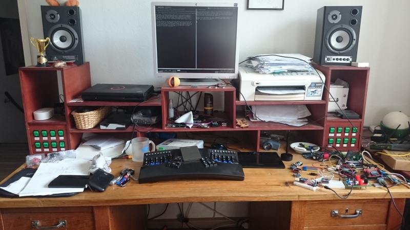
Great to have the pressure of these (repeatedly postponed) deadlines off my back, so I can finally take some time to do some long-due other stuff. Like cleaning up my desk:
Hello, yesterday I just bought your book and i have some questions about chapter 5.
Constantine, feel free to drop me a note at matthijs@stdin.nl with your questions!
Comments are closed for this story.
I originally wrote this, just under a year ago when I returned from this sailing trip. I found this draft post again a few weeks ago, being nearly finished. Since I'm about to leave on a new sailing trip next week (to France this time, if the wind permits), I thought it would be nice to finish this post before then. Even though it's a year old, the story is bizarre enough to publish it still :-)
I've put up photographs taken by me and Danny van den Akker up on Flickr.
Last year in May, I went on a 11 day sailing trip to the Isle of Wight an island off the southern coast of England. Together with my father, brother and two others on my father's boat as well as 10 other people on two more boats, we started out on this trip from Harderwijk on Thursday, navigating to the port of IJmuiden and going out on the north sea from there on Friday morning.
Initially, we had favourable wind and made good speed up to Dover at noon on Saturday. From then on, it seemed Murphy had climbed aboard our ship and we were in for our fair share of setbacks, partly balanced by some insane luck as well. In any case, here's a short timeline of the bad and lucky stuff:
- :-( Just around Beachy Head, our engine stopped running. We quickly
restarted it and carried on, but shortly after the engine stopped
again. It didn't want to start again either. In case you're wondering
- not having a working engine is a problem for a (bigger) sailing ship. Sailing into an (unknown) (sea) port is usually hard and on the open sea your engine is an important safety measure in case of problems.
- :-) Fortunately, Atlantis, one of our companion ships was only a few miles ahead (after having crossed most the North Sea through different routes, many miles apart). We sailed towards the port of New Haven, where they towed us into the port.
- :-( We diagnosed that there was a problem in the fuel supply, but couldn't find the real cause. We spent the sunday in the thrilling harbour town of New Haven, waiting for a mechanic to arrive.
- :-) On monday morning, a friendly mechanic called Neil fixed our fuel tank - it turned out there was a hose in there with a clogged filter as well as a kink near the end that prevented fuel from getting through. Neil cut off the end of the tube, fixing both problems at once and our engine ran again like a charm.
- :-( We continued towards Wight around noon, but shortly after passing No mans land Fort - guess what - our engine stopped running again.
- :-( This time we had no friends around to tow us in, but there was a Dutch ship (the Abel Tasman) nearby. We tried to get their attention using radio, a horn and a hand-held flare, but they misunderstood our intentions and carried on. We kept on sailing, but contacted the very much polite and helpful Solent Coast Guard by radio, to let them know we were coming in by sail and might needed a tow into the harbour.
- :-) After we finished our conversation with the Solent Coast Guard, the Abel Tasman hailed us on the radio and offered to tow us all the way to the harbor. With the wind dropping, we gladly accepted.
- :-) On monday evening We arrived on the Isle of Wight!
- :-) In the harbour, our engine started again (with some initial coughing). Yay for having a working engine, but without having fixed a problem, it could break down any moment. :-( We had some theories about what the problem could be, but no real confidence in any of them.
- :-) In the morning, we called for Tristan, a mechanic from the town Cowes where we were staying. He had a look at our engine, but since it was running again, there wasn't much he could do. He found a connection in the fuel line that wasn't very tight - guessing that that had allowed some air to slip into the fuel line. He tighted the connection and left us again.
- :-( Shortly after he left, we started the engine for a short refueling trip - and it stopped running again. We called for the mechanic to have another look, but he didn't show up all day...
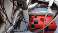
- :-( Near the end of the day, we didn't want to wait anymore and tried to bleed out the air from our engine, thinking that was the last problem. No matter how hard we tried, air nor fuel would come through. Debugging further, we found that the fuel tank would again not supply any fuel at all. We "fixed" this by disconnecting the fuel line, blowing into it and then sucking at it (credits to Jan-Peter for sucking up a mouthful of Diesel...). Together with the diesel there came also a wad of something that looked like mud.
- :-( Previously, we didn't suspect any pollution of our fuel tank, because the looking glass in the fuel filter was squeeky clean. Now, prompted by the gunk coming out of the tank, we opened up the filter to have a more thorough look and it turned out the filter was nearly completely filled with the same muddy stuff (which turned out to be "Diesel Bug" - various (byproducts of) bacteria and other organisms that like liveing in diesel tanks)
- :-) We didn't have a working engine yet, but at least we knew with confidence what the cause of our problems was, and had been. As Danny stated it: At least it is truely broken now. All we needed now was machinery to filter our fuel and rinse the inside of the tank.
- :-( On Tuesday, we found another mechanic who couldn't help us directly, but made a few phone calls. He found someone with the exact machinery we needed. The only problem was that the machinery was in the Swanwick Marina, on the UK mainland.
:-) On Wednesday, we tried to get into contact with the mechanic in Swanwick, to see if he could come over to Wight by ferry. We weren't hopeful, so in the meantime we also found a small plastic fuel tank (normally used for larger outboard motors) that could serve as a spare diesel tank. After also finding a few meters of diesel hose, getting an extra hose barb fitted and even getting a valve for fast on-the-fly switching between tanks (Thanks to Power Plus Marine Engineering for going out of their way to help us!), we had a working engine again by the end of the day!
We weren't confident our shiny new tank to sail all the way back to the Netherlands using it, but it would be more than sufficient to get over to Swanwick to get our main tank cleaned. As an extra bonus, it would be a good backup tank in case we still had problems after cleaning.
- :-) Early Thursday morning, we headed over to Swanwick where Geoffrey and Johnny laboured all morning to get a ton of sludge out of our tank. They sprayed the fuel back in using a narrow piece of pipe to clean the stuff off the edges of our tank as good as possible.
:-( As soon as they were done, we cast off and set course to
BrightonEastbourneDoverRamsgateDunkerque,Oostende,Zeebrugge, Dunkerque. Unfortunately, the wind direction was unfavorable (and later also didn't abide by the prediction, in our disadvantage of course), so we ended up sailing for only a small bit and using our engine most of the way.We changed our destination a few times along the way, usually because we thought "We might as well go on for a bit more, the further we go now, the easier it will be for the last stretch". Near Dunkerque, we planned to go on to Zeebrugge, but the wind picked up significantly. With the waves and wind against, we were getting a very rough ride, so we stopped at Dunkerque after all.
- :-( We came into port friday after office hours, so there was no personell anymore. In the restaurant we managed to get an access card so we could get to the toilet and back again, but the card had no balance, so we couldn't even take a shower...
- :-( Early saturday morning we carried on, this time with favorable wind direction, but not enough wind to make a decent speed. Since we lost all the slack in our schedule already (we had planned to be home by saturday afternoon), we used our engine again to make some speed.
:-( Shortly after crossing the Westerschelde, our engine stopped running again (can you believe that?). We quickly found that the engine itself would run fine, but would stop as soon as you put it into gear - there was something blocking up our screw propeller. Using Danny's GoPro underwater camera we confirmed that there was indeed something stuck in the screw. We didn't want to go into the water to fix it on open sea because of the safety risk, as well as the slim chance that we'd actually be able to cut out whatever was stuck.
:-) We contacted the coast guard again (the dutch one this time), telling them we'd sail towards the Roompot locks and would probably need a tow through the locks and into the harbour. We contacted the Burghsluis harbour and found they had a boat crane and were willing to operate it during the evening, so we had our target.
- :-( Then the wind dropped to nearly zero and we just floated around the North Sea for a bit. After an hour of floating, we contacted the coast guard and asked them to tow us in all the way - we were losing time quickly and with unreliable wind, there was no way we could safely cross the northern exit channel of the Westerschelde.
:-) While floating around a bit more, waiting for the coast guard to arrive, we slowly floated nearer to a small boat that we had previously seen in the distance already. Now, and this is where the story becomes even more unlikely, this boat was running a "diver flag", meaning there was a diver in the water nearby.
We slowly approached the boat and shortly after yelling over our problem to the woman on the boat, the diver emerged from the water. She told him of our problem, he swam over and under our boat and not even 30 seconds later he emerged again carrying a fairly short but thick piece of rope that had been stuck in our screw.
We started our engine and were on our way again, suffering about a 3-4 hour delay in total.
:-) We contacted the coast guard again to call them off, but they were already nearly there. To resolve some formalities, they continued heading our way. A minute or so later, the Koopmansdansk, a super-speedy boat from the KNRM came alongside. After we gave (read: Tried to yell over the roaring of their motor) them some contact information and the gave us a flyer about sponsoring the KNRM, we both went our separate ways again.
- :-( During the night, a thunderstorm came over us. I missed most of it because I was sleeping, but Jan Peter and Danny were completely drenched and attested that it was both heavy and somewhat scary due to the lightning.
- :-) Early sunday morning we went through the locks in IJmuiden, passed through Amsterdam and the Markermeer pretty uneventful. It even seemed like I would be at home just in time to head over to Enschede for our regular Glee night with some friends.
- :-( We were running low on diesel, so we had to find a place to fuel up in Lelystad. We found a harbour that was documented to have a gas pump, but didn't have one, so wasted some time finding one...
- :-( When we got to the locks of Roggebotsluis, it took a long time for the bridge to open. After floating around for 10 minutes or so, we noticed that one of the boom barriers (slagboom) looked warped and bent. Turns out just before we arrived there, some car got locked in between the barriers, panicked, hit the barrier while backing up and then sped away past the barrier on the opposite side. A mechanic was being summoned, but being a sunday...
- :-) After a short while, the bridge controller fellow came out, pulled the boom somewhat back into shape a bit and announced they'd give it a go. Thankfully for us, everything still worked and we were on our way!
- :-) No more delays after that. Brenda picked me up in the harbour, where I took a very quick shower before we headed to Enschede. Just in time for Glee, though I started falling asleep before we were even halfway. Apparently I was exhausted...
Overall, this was a crazy journey. All the problems we had have been a bit stressful and scary at times, but it was nice nonetheless. I especially enjoyed trying get things working again together, it was really a team effort.
Also interesting, especially for me, is that we had installed an AIS receiver on-board, which allows receiving information from nearby ships about their name, position, course and speed. This is especially useful in busy areas with lots of big cargo ships and to safely make your way through the big shipping lanes at sea.
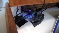
This AIS receiver needed to be wired up to the existing instruments and to my laptop, so we could view the information on our maps. So I spent most of the first day belowdecks figuring this stuff out. I continued fiddling with these connections and settings to improve the setup, running into some bugs and limitations. Knowing I might have to improvise, I had packed a few Arduinos, some basic electronics and an RS232 transceiver, which allowed me to essentially build a NMEA multiplexer that can forward some data and drop other data. Yay for building your own hardware and software while at sea. Also yay for not getting seasick easily :-p
Now, I'm getting ready for our next trip. We start, and possibly end, in Vlissingen this time (to buy a bit more time) and intend to go to Cherbourg. Let's hope this journey is a bit less "interesting" than the previous one!
I don't really have a well-defined plan for my professional carreer, but things keep popping up. A theme for this month seems to be "education".
I just returned from a day at Saxion hogeschool in Enschede, where I gave a lecture/workshop about programming Arduino boards without using the Arduino IDE or Arduino core code.
It was nice to be in front of students again and things went reasonably well. It's a bit different to engage non-academic (HBO) students and I didn't get around to telling and doing everything I had planned, but I have another followup lecture next week to improve on things.
At the same time, I'm currently talking with a publisher of technical books about writing a book about building wireless sensor networks with Arduino and XBee. I'll have to do some extensive research into the details of XBee for this, but I'm looking forward to see how I like writing such a technical book. If this blog is any indication, that should work out just fine.
For now, these are just small things next to my other work, but who knows what I'll come across next?
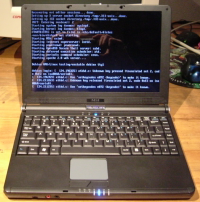
I was prompted to write this post after I got an email from another S270 user, thanking me for all the info I posted about these machines. He was also having power supply issues, with all the same resulting troubles I had (keyboard stuttering, USB issues, etc.).
He said he fixed this by simply replacing the notebook power supply and all his problems were gone. Interestingly I had already tried that and it didn't work for me, so we were having different problems.
Another reason for writing this post is that I actually fixed my power supply issues a few months ago. I can't really remember what prompted me too look into it again, but this time I didn't have anything to lose - I wasn't really using Xanthe for anything anymore. I opened up the casing completely, took out the mainboard to properly access the underside.
The power connector felt like it was fixed to the mainboard pretty tightly, but I put my soldering iron to it anyway. I just let the solder reflow nicely.
To my surprise, this actually worked. The power connector now powers the laptop properly, without any blinking. I suspect that the solder in one of the contacts had split and caused a flakey connection.
So, Xanthe is still idling around in a cabinet somewhere, but at least she's now usable as a backup or LARP prop sometime :-)
Last year, I got myself an Atmel JTAGICE3 programmer, in order to speed up programming my Pinoccio boards. This worked great, except that as can be expected of the tiny flatcable they used (1.27mm connector and even smaller flatcable), the cable broke within 6 months.
Atmel support didn't want to replace it, because it wasn't broken when I first unpacked the programmer, and told me to find and buy a new cable myself. Since finding these cables turns out to be tricky, and I didn't feel like breaking another cable in 6 months, I designed a converter board.
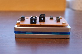
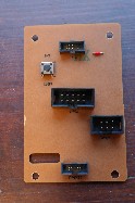
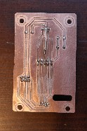
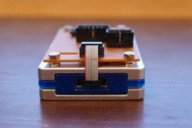
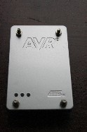
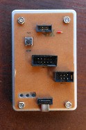
This board is a PCB to be mounted on top of the JTAGICE3, which can be connected permanently to the JTAGICE3 using a very short (1") flatcable, and converts to a "normal" (2.54mm pitch) connector for every-day use. It has both 10-pin JTAG and 6-pin ICSP headers, replacing the two converters that atmel ships. Additionally, the board has another 1.27mm pitch connector, so you can still connect target boards which also use this tiny connector. This still requires using a fragile cable, but now at least only when it's really needed. Finally, the board has a reset button, which can be used to reset the target board (useful for Pinoccio boards, which have none themselves).
Connector polarity
One odd thing about the JTAGICE3 is that the connector on the programmer itself is reversed wrt the polarity notch. Most flatcable connectors have a polarity key, with a matching notch in the socket, to prevent reversing the connector. Normally, the key and notch are at the side that has pin 1, but the JTAGICE3 has it reversed (rotated), so it's on the side that has pin 2. The flatcable that Atmel supplies also has one of the connectors reversed (it's actually upside down), which cancels out this reversion again.
This reversion actually makes it even harder to get a replacement cable, since most of the cables you can find in this size have both connectors applied normally.
Since I didn't want any of this reversed socket business on my board, I made sure to do the reversion in the cable between the JTAGICE3 and the converter board, and have all sockets on the board using the normal orientation.
This does mean that the original cable supplied by Atmel is now useless, even it hadn't broken, since it's way too long to connect the JTAGICE3 to the converter board, but connecting the converter board to a target that uses this tiny connector, needs a "straight" cable. The same goes for the squid cable, though that can still be used by manually correcting the pin numbers (1 becomes 10, 2 becomes 9, etc.).
Note that if you do want to keep using the reversed cable supplied by Atmel (perhaps because yours hasn't broken yet), that's just a matter of soldering on the JTAG2 socket rotated 180° (the notch is towards the board edge instead of toward the middle) - no need to change the PCB.
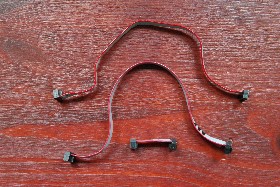
Above, there's a photo of the various flatcables. From top to bottom: original cable, with one connector upside-down, new regular cable, short cable with one connector reversed (effectively the same as upside-down).
Parts
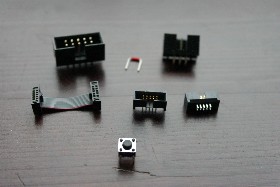
So, for this project, I needed:
- a custom-designed PCB
- a 2x5 pin shrouded pin header, regular 2.54mm spacing
- a 2x3 pin shrouded pin header, regular 2.54mm spacing
- two 2x5 pin shrouded pin headers, 1.27mm spacing (Samtec SHF-105-01-L-D-TH)
- a tiny, reversed flatcable (Samtec FFSD-05-D-01.00-01-N-RN2)
- a longer, non-reversed flatcable (Samtec FFSD-05-D-06.00-01-N)
- Some jumper wire
- Some bolts, nuts, copper standoff and insulating rings
For the half-pitched flatcables and connectors, I found that Samtec manufactures parts that fit the bill (though there should be others as well). I used their SHF series for the sockets, and FFSD series for the cables. Since I had some peculiar requirements (1" cable, reversed polarity key) and digikey only stocks a very limited number of products from their line, I ended up ordering what I needed as (free) samples from Samtec directly. There, you can just specify whatever parameters you need (once you figure out their part number system). Given the cables took a few days longer to ship, I believe they assembled them on demand for me. Thanks, Samtec!
Board design and milling
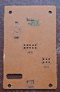
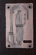
I designed the board in Kicad, my favorite open-source schematic and board tool. I had to design a custom footprint for the 1.27mm pitch connector, modify some other footprint to get 3mm mounting holes and I already had custom AVR-ICSP and AVR-JTAG pin header components (just normal headers, but with named pins), all else is just standard kicad stuff.
Since the board would cover up the status leds of the JTAGICE3, I added a cutout in the design, so you can still see the leds. I used pcb2gcode and a Mantis CNC mill to mill out the board, but I couldn't quite figure out how to get internal cutouts working properly. In the end, pcb2gcode would do the cutout, but it would mill on the outside of the cutout line instead of on the inside. I modified my design to shrink the cutout line by 1mm (size of my milling tool), so you might need to modify this line for your workflow if you want to create this board as well.
For connecting the 1.27mm connectors, I'm running traces in between the pins of the connector. This is really tiny stuff, which isn't conforming to my clearance requirements. This is intentional: If I reduced my clearance requirement or reduced the trace size, this would affect the traces everywhere on the board, not just the part where they run between the pins. By keeping the traces wide, pcb2gcode will also see a clearance violation but do its best to fulfill it by just milling exactly through the middle - which gives me the largest trace and pad size possible with my machine. You might need to modify this a bit for your workflow.
Because squeezing in these traces reduces the width of these pads significantly (in a few places they're no wider than the holes), I modified the footprint to make the pads a bit higher, so you at least have some area left for soldering.
After milling the board, and applying the silkscreen markings using a lasercutter, I realized I had forgotten markers for pin 1 on the connectors. I've fixed this in the design, for anyone else to benefit.
For a lot more info about milling PCBs using a Mantis CNC mill, see this page at fablabamersfoort. It's an ongoing report of my experiments. It is written in Dutch, though.
I made the board design available on github, for anyone else to play with.
Assembly
Soldering the board was easy, though some of the traces ended up a bit small because I'm running against the limits of my CNC mill. One trace actually got destroyed while soldering, so I fixed that using a piece of wire on the copper side.
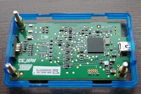
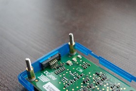
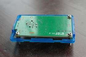
To mount the board on top of the JTAGICE3, I had to make a few modifications to the programmer. The original PCB in the JTAGICE3 already had three (unused) mounting holes, which I could conveniently use. I found some 8mm high copper standoffs, which together with a 1.5mm plastic ring (for insulation) fit snugly between the original PCB and the top of the casing.
I slightly enlarged the mounting holes in the original PCB to 3mm, so I could fit standard M3 bolts. I also drilled 3mm holes in the top side of the casing, to match the mounting holes. I also needed to mill away a bit of plastic from the inside of the bottom casing, just below the three mounting holes, to make room for the head of the bolt.
To solidly fix the new board, I used a fourth mounting hole in my own PCB, which only attaches to the JTAGICE3 casing, not the original PCB.
During assembly, it turned out that my cutout was positioned slightly too high. I already corrected this in the board design I published, so that one should be good.
The end result is an elegant and solid extension of the programmer, with easily accessible connectors. There's still a tiny ribbon cable in there, but it fits perfectly and should never be under much stress. Now, back to actual work :-p
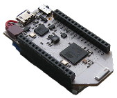
The Pinoccio Scout is a wonderful Arduino-like microcontroller board that has builtin mesh networking, a small form factor and a ton of resources (at least in Arduino terms: 32K of SRAM and 256K of flash).
However, flashing a new program into the scout happens through a serial port at 115200 baud. That's perfectly fine when you only have 32K of flash or for occasional uploads. But when you upload a 100k+ program dozens of times per day, it turns out that that's actually really slow! Uploading and verifying a 104KiB sketch takes over 30 seconds, just too long to actually wait for it (so you do something else, get distracted, and gone is the productivity).
$ time avrdude -p atmega256rfr2  -cwiring -P/dev/ttyACM0 -b115200 -D -Uflash:w:Bootstrap.cpp.hex:i

avrdude: AVR device initialized and ready to accept instructions

Reading | ################################################## | 100% 0.01s

avrdude: Device signature = 0x1ea802
avrdude: reading input file "Bootstrap.cpp.hex"
avrdude: writing flash (106654 bytes):

Writing | ################################################## | 100% 18.80s

avrdude: 106654 bytes of flash written
avrdude: verifying flash memory against Bootstrap.cpp.hex:
avrdude: load data flash data from input file Bootstrap.cpp.hex:
avrdude: input file Bootstrap.cpp.hex contains 106654 bytes
avrdude: reading on-chip flash data:

Reading | ################################################## | 100% 13.51s

avrdude: verifying ...
avrdude: 106654 bytes of flash verified

avrdude: safemode: Fuses OK (H:DE, E:10, L:DE)

avrdude done.  Thank you.

real    0m32.824s
user    0m0.120s
sys     0m0.560s
Using an external (ISP) programmer is supposed to be faster. I had an STK500 development board to use, but that's also connected to my PC through a 115200 baud serial port, so no help there.
$ time avrdude -patmega256rfr2 -cstk500v2 -P/dev/serial/stk500 -b115200 -D -Uflash:w:Bootstrap.cpp.hex:i
(...)
real    0m27.523s
So, I got myself a JTAGICE3 programmer, which as an added bonus can do in-circuit debugging as well (e.g. stepping through the code, dumping variables). After setting up the udev permission rules on my Linux system, I used a bunch of jumper wires to hook the JTAG3ICE to the ISP/SPI pins of my Scout.
VTARGET pin
| SPI pin | Function | Pinoccio pin |
|---|---|---|
| 1 | MISO | MISO |
| 2 | VTARGET | SCL (through diode) |
| 3 | SCK | SCK |
| 4 | MOSI | MOSI |
| 5 | /RESET | RST |
| 6 | GND | GND |
One pin was particularly cumbersome: the VTARGET pin. On my STK500 board, this pin supplies a configurable voltage, to power the target board. However, on the Scout, there is no direct access to the VCC line on the pin headers (the 3V3 pin is the output from a secondary regulator, not connected to the main MCU's VCC and it cannot be used as a power input).
I tried powering the board through the USB cable as normal and leaving VTARGET pin on my JTAG3ICE disconnected, but that didn't work. Interestingly enough, using the 6-pin ISP "connector" (no pins, only pads) on the bottom of my scout did work right away.
It turns out the JTAGICE3 doesn't actually provide power on the VTARGET pin. Instead, it uses the pin to sample the target's voltage, so it can drive its data pins at the same voltage as the target, without needing to explicitly configure the voltage. This posed me with a challenge: I needed to put 3.3V on the VTARGET pin, but the 3V3 pin needs to be explicitely enabled by the Scout (and gets turned off when the AVR MCU is held in reset during ISP programming).
Fortunately, the SDA, SCL and BKP (backpack bus) pins contain a pull-up resistor. When nothing else is connected to this pins, their voltage is approximately VCC. Connecting VTARGET to one of these made things work!
Update: It seems that connecting VTARGET to BKP doesn't work, since its pullup resistor is big (100kΩ) and the VTARGET pin draws about 15 μA, resulting in a 1.5V voltage drop.
Connecting VTARGET to SDA or SCL prevents I²C from working properly when the JTAGICE3 is still connected, it seems like the JTAGICE3 acts like a capacitor, keeping the pins high and messing up the signals. Adding a 10k resistor helps to fix the I²C, but breaks JTAG programming again for reasons I don't full grasp. However, adding a diode (I used an 1N4148) between SCL and VTARGET (connected such that current can flow from SCL to VTARGET but not the other way around) fixes everything. This does mean the actual programming happens at 2.8V due to the diode voltage drop, but that's still more than enough.
$ time avrdude -patmega256rfr2 -cjtag3isp -B1 -D -Uflash:w:Bootstrap.cpp.hex:i
(...)
real    0m17.280s
Note the -B1 option, which selects the fastest SPI speed supported by the JTAGICE3 (You can also just pass a lower number, which should also use the fastest supported speed, according to the avrdude sources).
This is already a bit better, but still not as good as I'd want.
Using JTAG
| JTAG pin | Function | Pinoccio pin |
|---|---|---|
| 1 | TCK | A4 |
| 2 | GND | GND |
| 3 | TDO | A6 |
| 4 | VTG | SCL (through diode) |
| 5 | TMS | A5 |
| 6 | nSRST | RST |
| 7 | - | - |
| 8 | nTRST | - |
| 9 | TDI | A7 |
| 10 | GND | GND |
Until now, we used ISP which talks to the target chip over the SPI pins (MISO/MOSI/SCK) and is limited to 1Mhz operation on the JTAGICE3. However, you can also program this AVR chip using JTAG, a protocol originally designed for debugging. Using JTAG, the JTAGICE3 can run up to 10Mhz according to avrdude. This isn't 10x as fast as ISP (probably because JTAG has more protocol overhead), but the speedup is significant.
Before we can do JTAG, though, we'll have to enable (switch to 0) the JTAGEN fuse in the atmega256rfr2. We can do this using the JTAG3ICE's SPI mode:
$ avrdude -p atmega256rfr2 -c jtag3isp -U hfuse:w:0x10:m
Note that this fuse setting is specific to the Pinoccio Scout / Atmega256rfr2. If you have another device, check the datasheet for the correct fuse settings. Furthermore, this fuse setting also programs the OCDEN (on-chip debugging) fuse, though I haven't actually tried to use it. Keep in mind that with the JTAGEN fuse enabled, you can't use the JTAG pins for other purposes. Also, enabling the JTAGEN and OCDEN fuses increases power usage.
After enabling the fuse, I can flash sketches through the JTAG pins (which are mapped to A4-A7 on the Scout):
$ time avrdude -patmega256rfr2 -cjtag3 -B0.1 -D -Uflash:w:Bootstrap.cpp.hex:i
(...)
real    0m6.715s
Yeah, now we're talking!
Note again the -B option, for which 0.1 seems the fastest value for JTAG (though these values are a bit finniky, it seems that the JTAGICE3 firmware does some manipulation with this value).
Proper headers
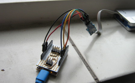
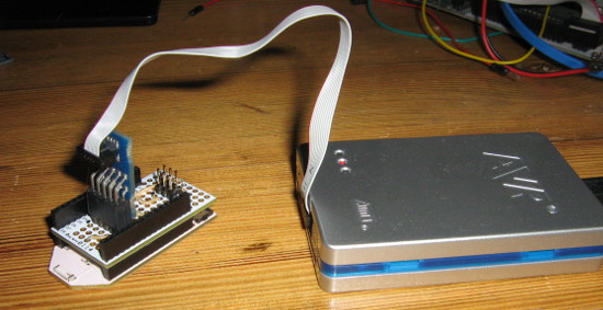
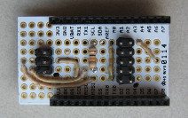
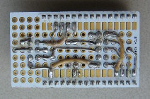
However, having to plug in 6 or 7 jumper wires whenever I want to flash a different board is a bit cumbersome (especially having to remember which wire goes where). Having proper headers (6-pin ISP header and a 10-pin JTAG header) would help here. This is where the Pinoccio Protoboard comes in: it's essentially a DIY backpack that you can solder components - or connectors - onto. After figuring out the pinout puzzle (so many crossed wires, good that these boards have two sides!) I ended up with this piece of work:
I marked pin 1 with a small black dot, which is commonly done with these kinds of connectors.
Next up: figuring out the debugging support using avrice on Linux, or if that doesn't work, Atmel Studio on Windows...
Update: The SVN version from avarice supports the JTAGICE3, so I can single-step through my code using gdb :-D
Update: I've been working on a proper PCB design for this board (since I needed one or two more). I haven't actually built one yet, but the design so far is available on github. See below for the rendered schematic and board files.

Hi Matthijis
Thanks for this useful piece. "Also, enabling the JTAGEN and OCDEN fuses increases power usage." Can I disable the fuse after I prototype with it to lower power usage?
Yes, if you disable the fuse again, the power usage will drop back to normal (and of course you can no longer access the chip through JTAG anymore).
Hey Matthijs
Do you think you can release a simplified schematics for the protoboard connections?
Incidentally, I was already working on a proper PCB design for this, so I had a schematic lying around already (planning to publish things once I got the first working PCB milled). But, now that you asked, I cleaned up the schematic a bit and published stuff right away, see the update in the post above.
Thanks for your interest! Let me know if you build one yourself!
Comments are closed for this story.









Comments are closed for this story.