These are the ramblings of Matthijs Kooijman, concerning the software he hacks on, hobbies he has and occasionally his personal life.
Most content on this site is licensed under the WTFPL, version 2 (details).
Questions? Praise? Blame? Feel free to contact me.
My old blog (pre-2006) is also still available.
See also my Mastodon page.
| Sun | Mon | Tue | Wed | Thu | Fri | Sat |
|---|---|---|---|---|---|---|
| 1 | 2 | 3 | ||||
| 4 | 5 | 6 | 7 | 8 | 9 | 10 |
| 11 | 12 | 13 | 14 | 15 | 16 | 17 |
| 18 | 19 | 20 | 21 | 22 | 23 | 24 |
| 25 | 26 | 27 | 28 | 29 | 30 | 31 |
(...), Arduino, AVR, BaRef, Blosxom, Book, Busy, C++, Charity, Debian, Electronics, Examination, Firefox, Flash, Framework, FreeBSD, Gnome, Hardware, Inter-Actief, IRC, JTAG, LARP, Layout, Linux, Madness, Mail, Math, MS-1013, Mutt, Nerd, Notebook, Optimization, Personal, Plugins, Protocol, QEMU, Random, Rant, Repair, S270, Sailing, Samba, Sanquin, Script, Sleep, Software, SSH, Study, Supermicro, Symbols, Tika, Travel, Trivia, USB, Windows, Work, X201, Xanthe, XBee
 &
&
(With plugins: config, extensionless, hide, tagging, Markdown, macros, breadcrumbs, calendar, directorybrowse, entries_index, feedback, flavourdir, include, interpolate_fancy, listplugins, menu, pagetype, preview, seemore, storynum, storytitle, writeback_recent, moreentries)
Valid XHTML 1.0 Strict & CSS
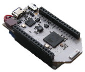
The Pinoccio Scout is a wonderful Arduino-like microcontroller board that has builtin mesh networking, a small form factor and a ton of resources (at least in Arduino terms: 32K of SRAM and 256K of flash).
However, flashing a new program into the scout happens through a serial port at 115200 baud. That's perfectly fine when you only have 32K of flash or for occasional uploads. But when you upload a 100k+ program dozens of times per day, it turns out that that's actually really slow! Uploading and verifying a 104KiB sketch takes over 30 seconds, just too long to actually wait for it (so you do something else, get distracted, and gone is the productivity).
$ time avrdude -p atmega256rfr2  -cwiring -P/dev/ttyACM0 -b115200 -D -Uflash:w:Bootstrap.cpp.hex:i

avrdude: AVR device initialized and ready to accept instructions

Reading | ################################################## | 100% 0.01s

avrdude: Device signature = 0x1ea802
avrdude: reading input file "Bootstrap.cpp.hex"
avrdude: writing flash (106654 bytes):

Writing | ################################################## | 100% 18.80s

avrdude: 106654 bytes of flash written
avrdude: verifying flash memory against Bootstrap.cpp.hex:
avrdude: load data flash data from input file Bootstrap.cpp.hex:
avrdude: input file Bootstrap.cpp.hex contains 106654 bytes
avrdude: reading on-chip flash data:

Reading | ################################################## | 100% 13.51s

avrdude: verifying ...
avrdude: 106654 bytes of flash verified

avrdude: safemode: Fuses OK (H:DE, E:10, L:DE)

avrdude done.  Thank you.

real    0m32.824s
user    0m0.120s
sys     0m0.560s
Using an external (ISP) programmer is supposed to be faster. I had an STK500 development board to use, but that's also connected to my PC through a 115200 baud serial port, so no help there.
$ time avrdude -patmega256rfr2 -cstk500v2 -P/dev/serial/stk500 -b115200 -D -Uflash:w:Bootstrap.cpp.hex:i
(...)
real    0m27.523s
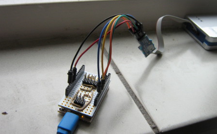
So, I got myself a JTAGICE3 programmer, which as an added bonus can do in-circuit debugging as well (e.g. stepping through the code, dumping variables). After setting up the udev permission rules on my Linux system, I used a bunch of jumper wires to hook the JTAG3ICE to the ISP/SPI pins of my Scout.
VTARGET pin
| SPI pin | Function | Pinoccio pin |
|---|---|---|
| 1 | MISO | MISO |
| 2 | VTARGET | SCL (through diode) |
| 3 | SCK | SCK |
| 4 | MOSI | MOSI |
| 5 | /RESET | RST |
| 6 | GND | GND |
One pin was particularly cumbersome: the VTARGET pin. On my STK500 board, this pin supplies a configurable voltage, to power the target board. However, on the Scout, there is no direct access to the VCC line on the pin headers (the 3V3 pin is the output from a secondary regulator, not connected to the main MCU's VCC and it cannot be used as a power input).
I tried powering the board through the USB cable as normal and leaving VTARGET pin on my JTAG3ICE disconnected, but that didn't work. Interestingly enough, using the 6-pin ISP "connector" (no pins, only pads) on the bottom of my scout did work right away.
It turns out the JTAGICE3 doesn't actually provide power on the VTARGET pin. Instead, it uses the pin to sample the target's voltage, so it can drive its data pins at the same voltage as the target, without needing to explicitly configure the voltage. This posed me with a challenge: I needed to put 3.3V on the VTARGET pin, but the 3V3 pin needs to be explicitely enabled by the Scout (and gets turned off when the AVR MCU is held in reset during ISP programming).
Fortunately, the SDA, SCL and BKP (backpack bus) pins contain a pull-up resistor. When nothing else is connected to this pins, their voltage is approximately VCC. Connecting VTARGET to one of these made things work!
Update: It seems that connecting VTARGET to BKP doesn't work, since its pullup resistor is big (100kΩ) and the VTARGET pin draws about 15 μA, resulting in a 1.5V voltage drop.
Connecting VTARGET to SDA or SCL prevents I²C from working properly when the JTAGICE3 is still connected, it seems like the JTAGICE3 acts like a capacitor, keeping the pins high and messing up the signals. Adding a 10k resistor helps to fix the I²C, but breaks JTAG programming again for reasons I don't full grasp. However, adding a diode (I used an 1N4148) between SCL and VTARGET (connected such that current can flow from SCL to VTARGET but not the other way around) fixes everything. This does mean the actual programming happens at 2.8V due to the diode voltage drop, but that's still more than enough.
$ time avrdude -patmega256rfr2 -cjtag3isp -B1 -D -Uflash:w:Bootstrap.cpp.hex:i
(...)
real    0m17.280s
Note the -B1 option, which selects the fastest SPI speed supported by the JTAGICE3 (You can also just pass a lower number, which should also use the fastest supported speed, according to the avrdude sources).
This is already a bit better, but still not as good as I'd want.
Using JTAG
| JTAG pin | Function | Pinoccio pin |
|---|---|---|
| 1 | TCK | A4 |
| 2 | GND | GND |
| 3 | TDO | A6 |
| 4 | VTG | SCL (through diode) |
| 5 | TMS | A5 |
| 6 | nSRST | RST |
| 7 | - | - |
| 8 | nTRST | - |
| 9 | TDI | A7 |
| 10 | GND | GND |
Until now, we used ISP which talks to the target chip over the SPI pins (MISO/MOSI/SCK) and is limited to 1Mhz operation on the JTAGICE3. However, you can also program this AVR chip using JTAG, a protocol originally designed for debugging. Using JTAG, the JTAGICE3 can run up to 10Mhz according to avrdude. This isn't 10x as fast as ISP (probably because JTAG has more protocol overhead), but the speedup is significant.
Before we can do JTAG, though, we'll have to enable (switch to 0) the JTAGEN fuse in the atmega256rfr2. We can do this using the JTAG3ICE's SPI mode:
$ avrdude -p atmega256rfr2 -c jtag3isp -U hfuse:w:0x10:m
Note that this fuse setting is specific to the Pinoccio Scout / Atmega256rfr2. If you have another device, check the datasheet for the correct fuse settings. Furthermore, this fuse setting also programs the OCDEN (on-chip debugging) fuse, though I haven't actually tried to use it. Keep in mind that with the JTAGEN fuse enabled, you can't use the JTAG pins for other purposes. Also, enabling the JTAGEN and OCDEN fuses increases power usage.
After enabling the fuse, I can flash sketches through the JTAG pins (which are mapped to A4-A7 on the Scout):
$ time avrdude -patmega256rfr2 -cjtag3 -B0.1 -D -Uflash:w:Bootstrap.cpp.hex:i
(...)
real    0m6.715s
Yeah, now we're talking!
Note again the -B option, for which 0.1 seems the fastest value for JTAG (though these values are a bit finniky, it seems that the JTAGICE3 firmware does some manipulation with this value).
Proper headers
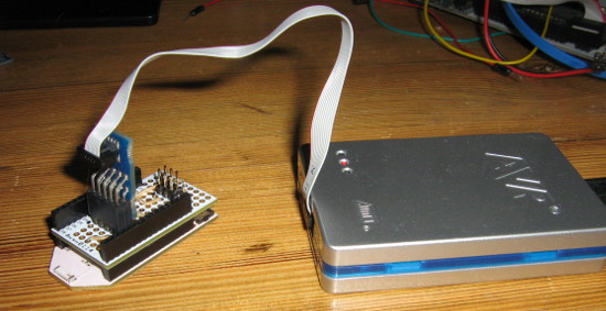
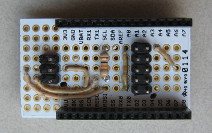
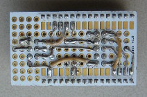
However, having to plug in 6 or 7 jumper wires whenever I want to flash a different board is a bit cumbersome (especially having to remember which wire goes where). Having proper headers (6-pin ISP header and a 10-pin JTAG header) would help here. This is where the Pinoccio Protoboard comes in: it's essentially a DIY backpack that you can solder components - or connectors - onto. After figuring out the pinout puzzle (so many crossed wires, good that these boards have two sides!) I ended up with this piece of work:
I marked pin 1 with a small black dot, which is commonly done with these kinds of connectors.
Next up: figuring out the debugging support using avrice on Linux, or if that doesn't work, Atmel Studio on Windows...
Update: The SVN version from avarice supports the JTAGICE3, so I can single-step through my code using gdb :-D
Update: I've been working on a proper PCB design for this board (since I needed one or two more). I haven't actually built one yet, but the design so far is available on github. See below for the rendered schematic and board files.



Hi Matthijis
Thanks for this useful piece. "Also, enabling the JTAGEN and OCDEN fuses increases power usage." Can I disable the fuse after I prototype with it to lower power usage?
Yes, if you disable the fuse again, the power usage will drop back to normal (and of course you can no longer access the chip through JTAG anymore).
Hey Matthijs
Do you think you can release a simplified schematics for the protoboard connections?
Incidentally, I was already working on a proper PCB design for this, so I had a schematic lying around already (planning to publish things once I got the first working PCB milled). But, now that you asked, I cleaned up the schematic a bit and published stuff right away, see the update in the post above.
Thanks for your interest! Let me know if you build one yourself!
Comments are closed for this story.