
These are the ramblings of Matthijs Kooijman, concerning the software he hacks on, hobbies he has and occasionally his personal life.
Most content on this site is licensed under the WTFPL, version 2 (details).
Questions? Praise? Blame? Feel free to contact me.
My old blog (pre-2006) is also still available.
See also my Mastodon page.
| Sun | Mon | Tue | Wed | Thu | Fri | Sat |
|---|---|---|---|---|---|---|
| 1 | 2 | 3 | 4 | 5 | ||
| 6 | 7 | 8 | 9 | 10 | 11 | 12 |
| 13 | 14 | 15 | 16 | 17 | 18 | 19 |
| 20 | 21 | 22 | 23 | 24 | 25 | 26 |
| 27 | 28 | 29 | 30 | 31 |
(...), Arduino, AVR, BaRef, Blosxom, Book, Busy, C++, Charity, Debian, Electronics, Examination, Firefox, Flash, Framework, FreeBSD, Gnome, Hardware, Inter-Actief, IRC, JTAG, LARP, Layout, Linux, Madness, Mail, Math, MS-1013, Mutt, Nerd, Notebook, Optimization, Personal, Plugins, Protocol, QEMU, Random, Rant, Repair, S270, Sailing, Samba, Sanquin, Script, Sleep, Software, SSH, Study, Supermicro, Symbols, Tika, Travel, Trivia, USB, Windows, Work, X201, Xanthe, XBee
 &
&
(With plugins: config, extensionless, hide, tagging, Markdown, macros, breadcrumbs, calendar, directorybrowse, entries_index, feedback, flavourdir, include, interpolate_fancy, listplugins, menu, pagetype, preview, seemore, storynum, storytitle, writeback_recent, moreentries)
Valid XHTML 1.0 Strict & CSS
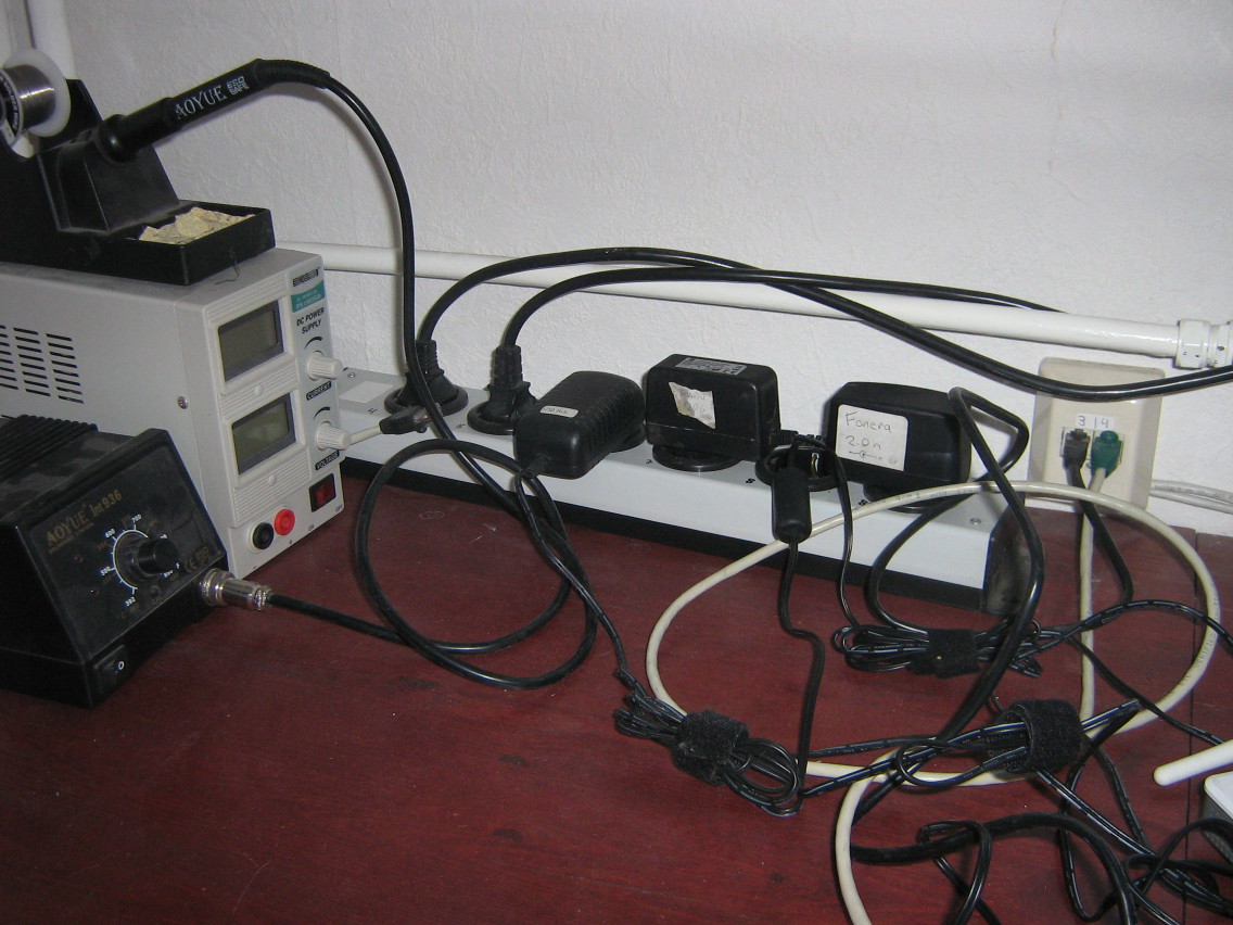
Since ages, I've been using switched power bars to connect my computer equipment. Originally, I used a normal outlet to connect my PC and a switched bar to connect my monitor, speakers, printer, etc. This allows me to actually completely switch off everything when I'm not using it, saving a couple of Watts of leakage power and removing the need to switch all of my equipment off separately.
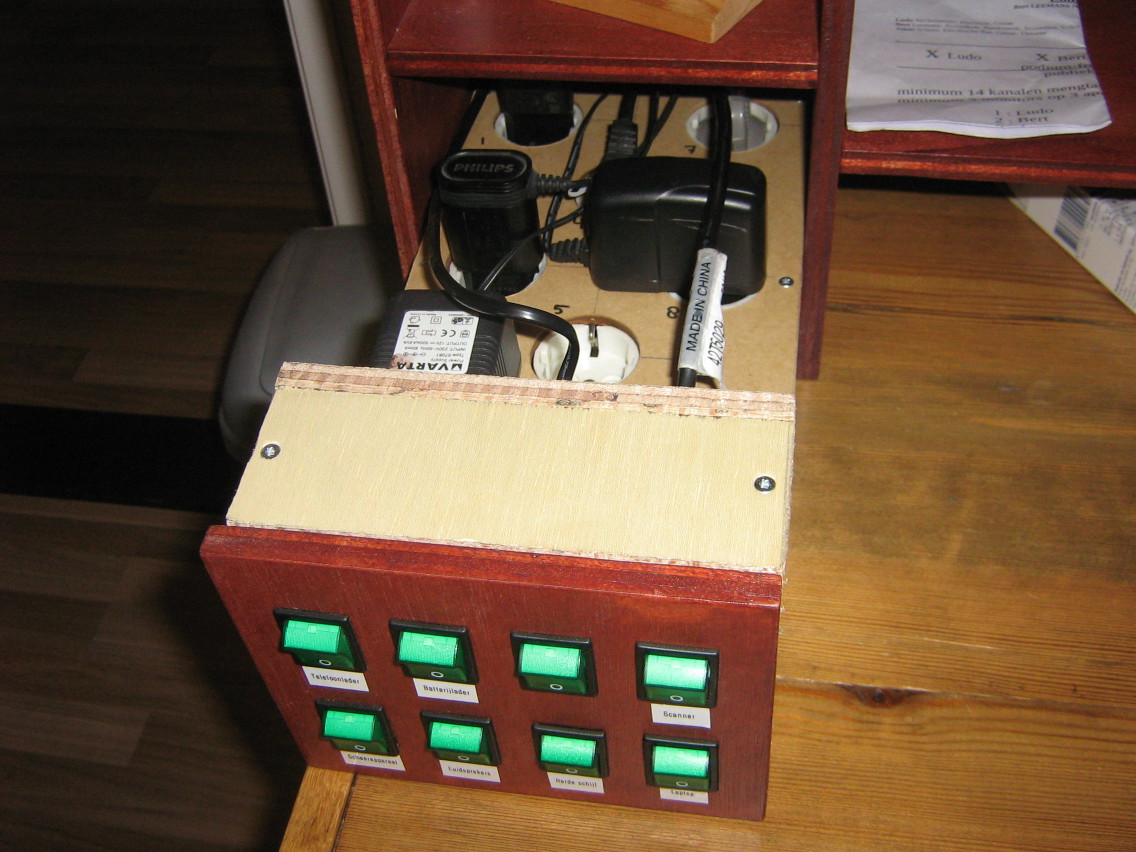
Since then, the amount of electrical stuff on my desk has increased a bit, now also including quite some stuff unrelated to my computer. I now count: a laptop adapter, an USB hub, speakers, a printer/scanner, an external hard disk, a battery charger, a phone charger, a charger for my shaver, some soldering equipment, a pile of wireless access points (my work for Fon).
Plugging in all this stuff in a single power bar wasn't very helpful: I would have the bar turned on most of the day when working on my laptop, so all the other devices would be leaking power as well.

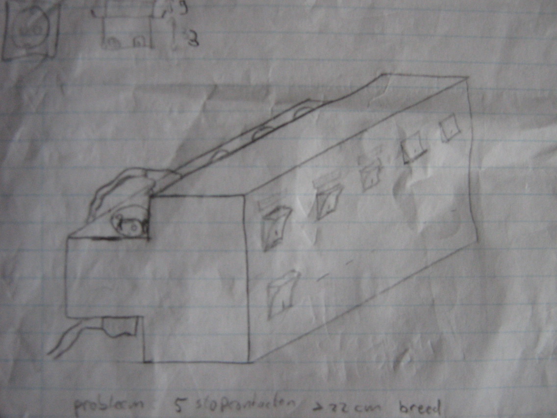
It thought I found the perfect solution when I found this power bar with five individually switched outlets from Brennenstuhl. However, because both the switches and the outlets need some space, this power bar is pretty huge (±60 cm long), making it pretty impossible to give it a useful place on my desk (without taking up too much desk space), so I would have to think of something else.
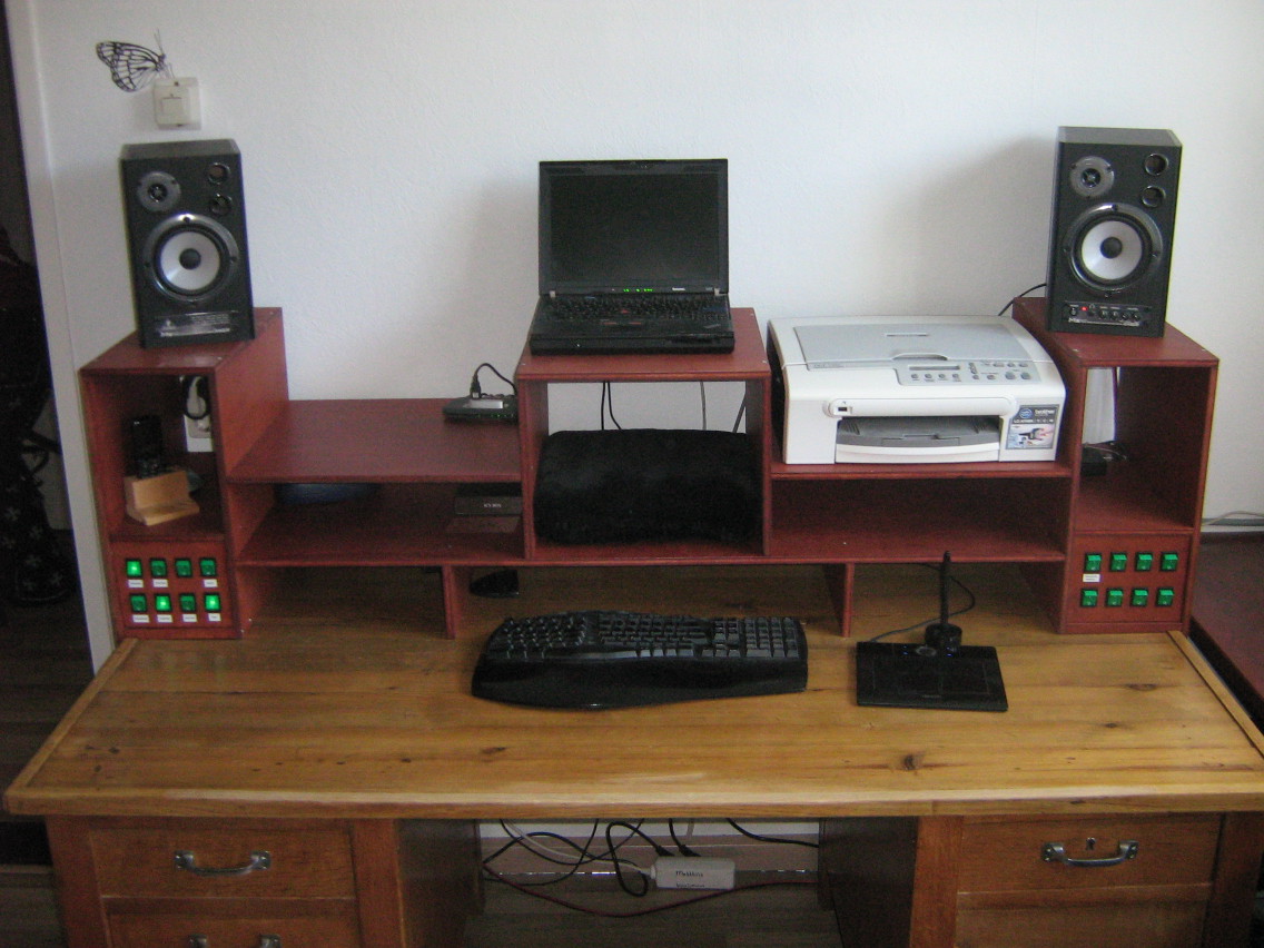
I have been thinking about building a nice cabinet to put on top of my desk to put my laptop, speakers and printer on top of and to put various paperwork and other misc items in (to replace the cardboard boxes that kept my laptop at an ergonomical height until then). In the design of that cabinet, I realized that I could just as well include some power switch panels in the cabinet.
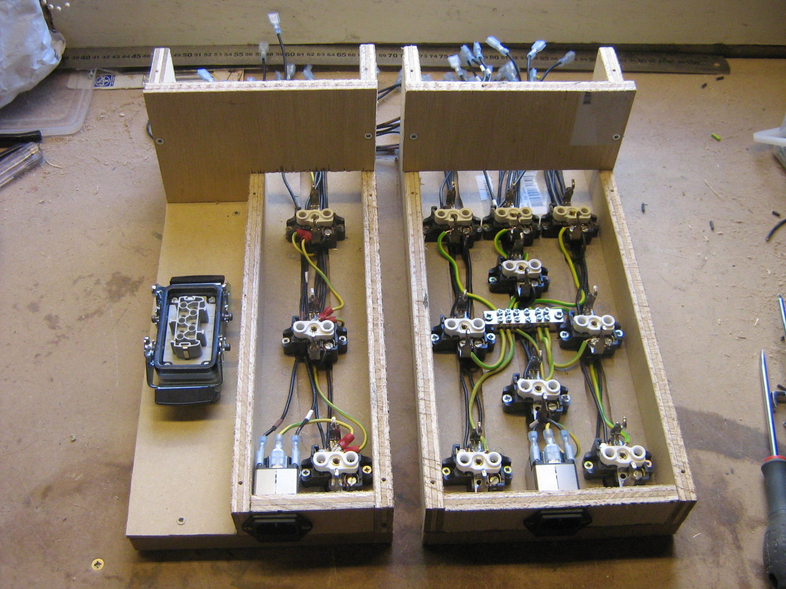
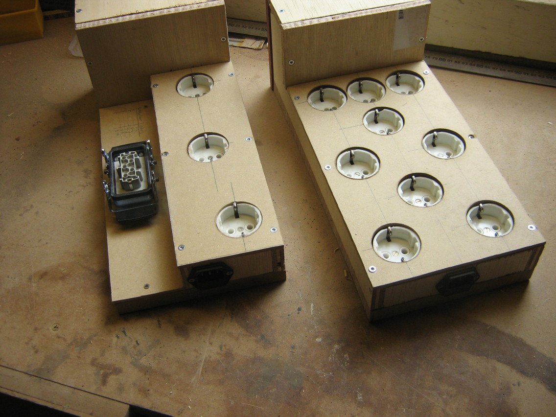
After a few iterations of the design, I ended up with the following result:
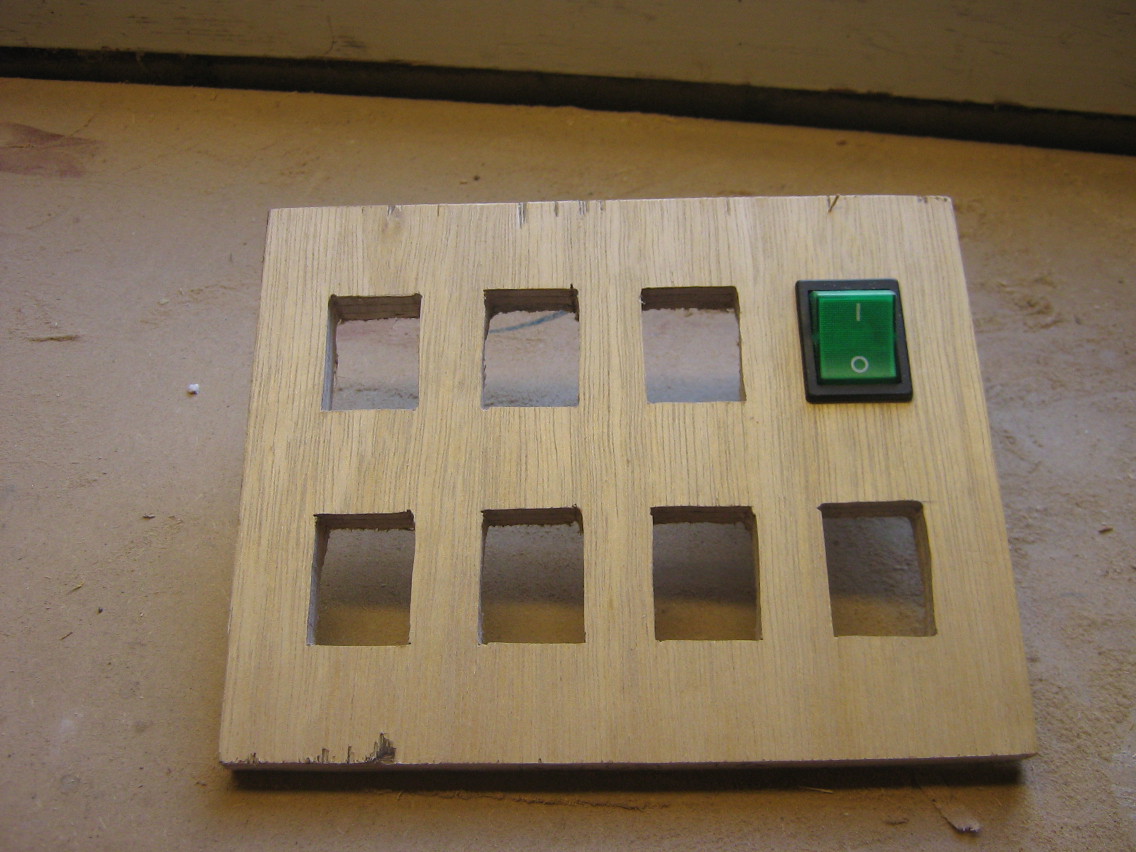
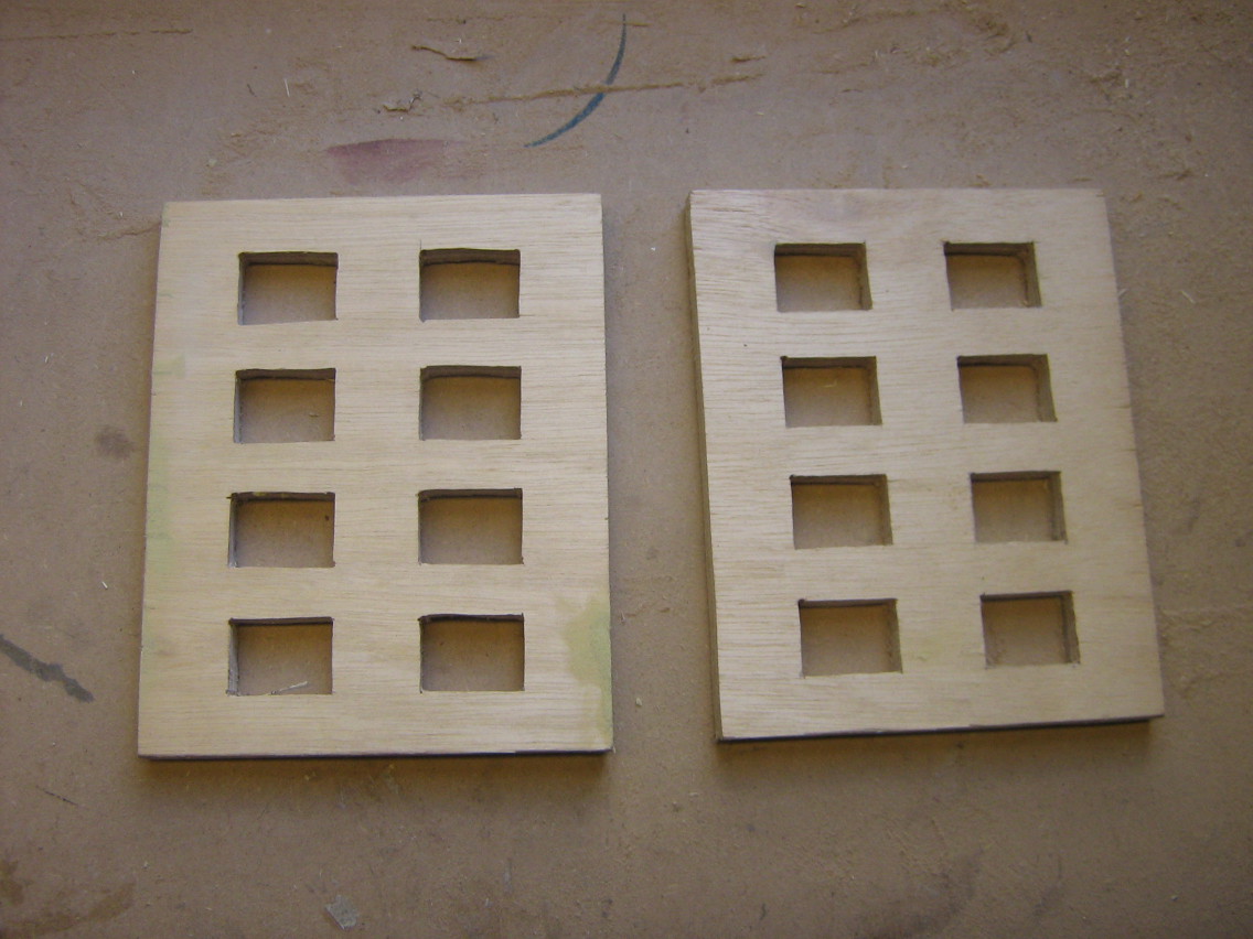
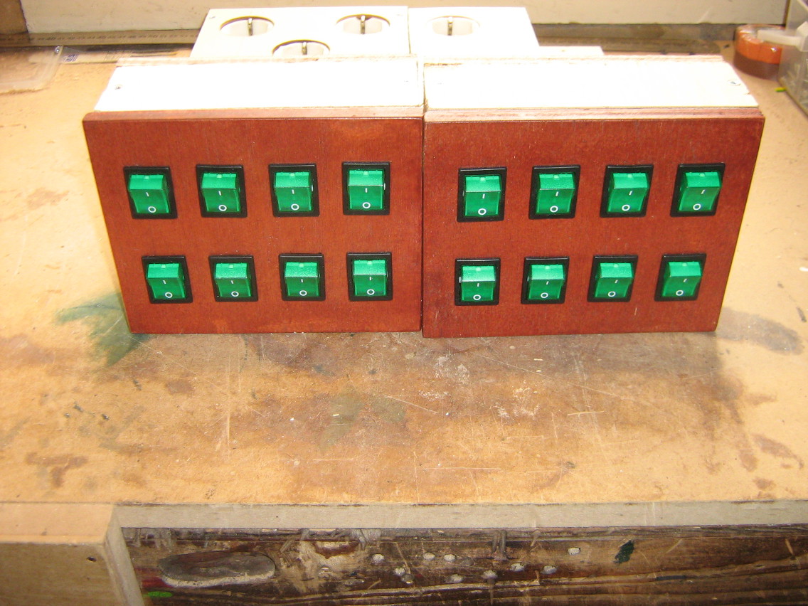
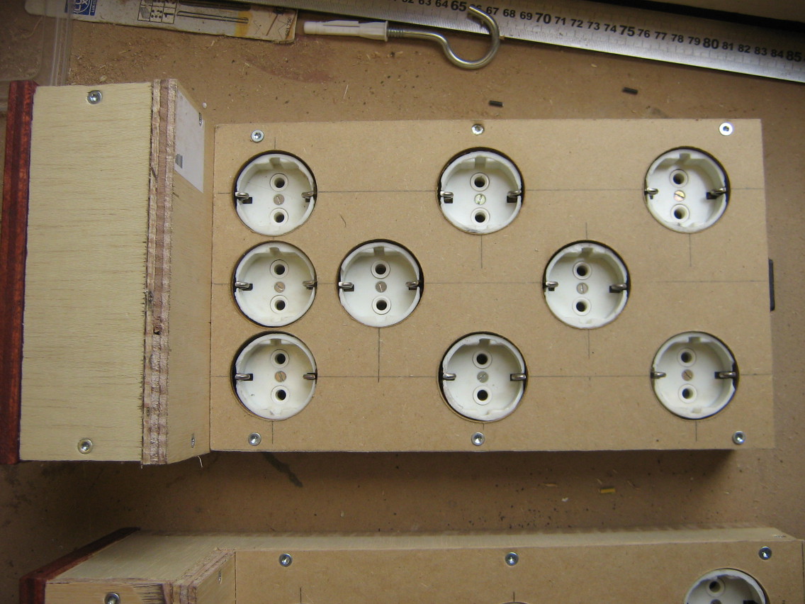
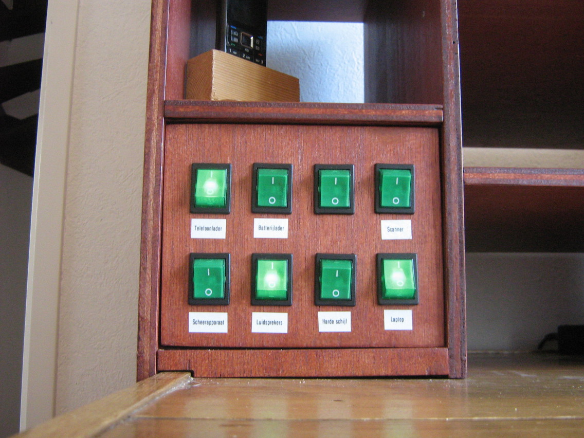
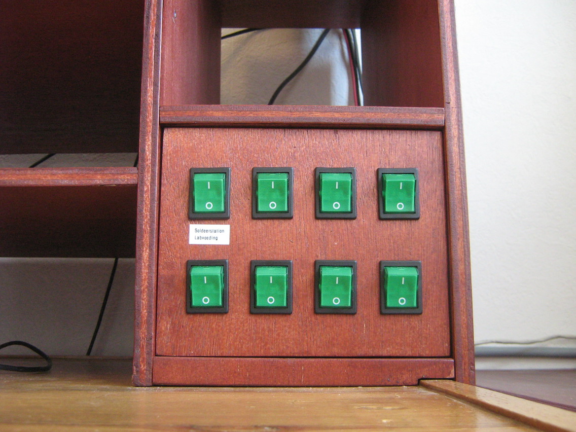
As you can see, there's two switch panels with eight switches each in the lower corners. Each switch controls one or two outlets, most of which are hidden behind the panels. Since most of the devices don't move around much, it's perfect if the outlets and plugs are hidden inside the cabinet, since that means less cluttering of my desk.
However, I also have some devices (mostly wireless access points, settopboxes and monitors that I use for my work) that are not fixed all the time and regularly change. If I would need to get behind the switch panels everytime I wanted to change a device, I would get tired of that real quick. I could of course have used a completely separate outlet bar for those devices, but I still like to make those devices individually switched (since most of them have power adapters, which are prone to leak power, and I hardly ever use all of the devices at the same time).
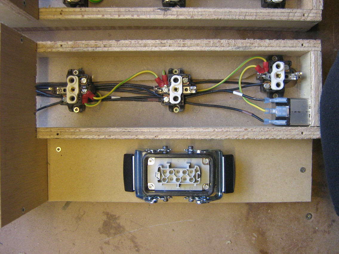
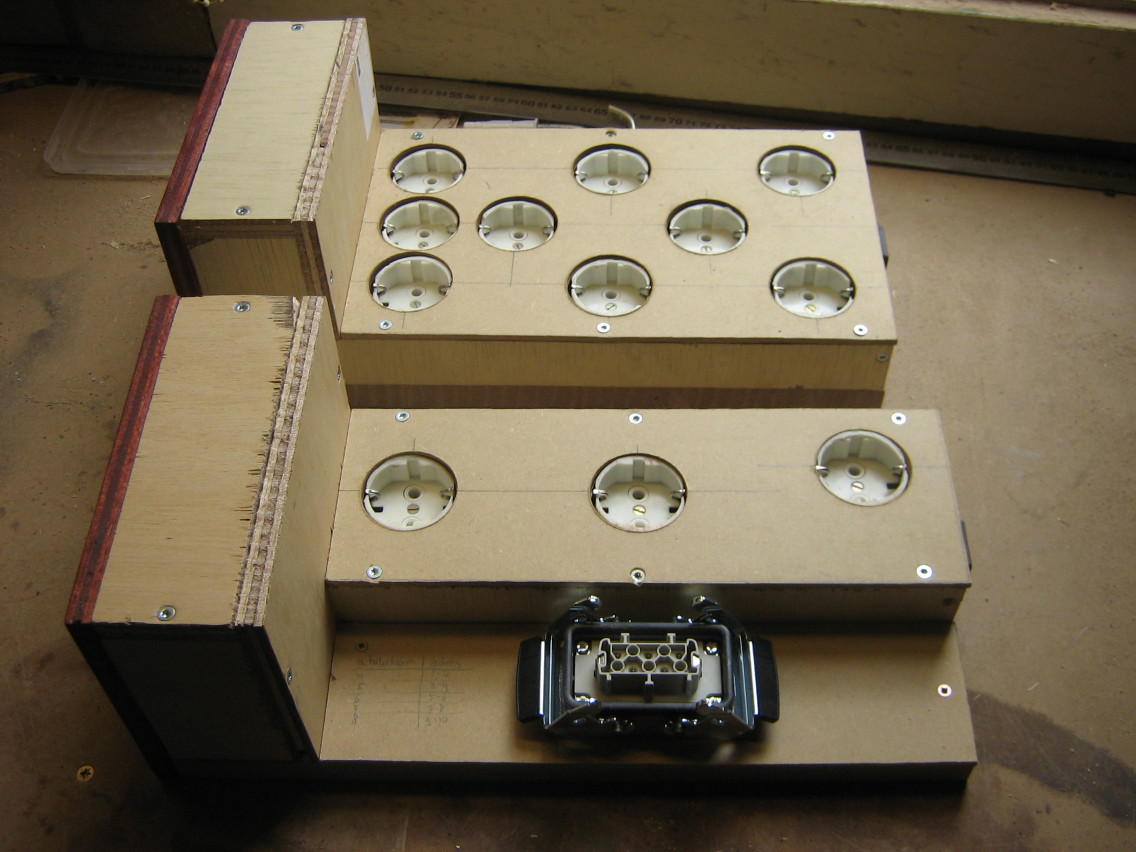
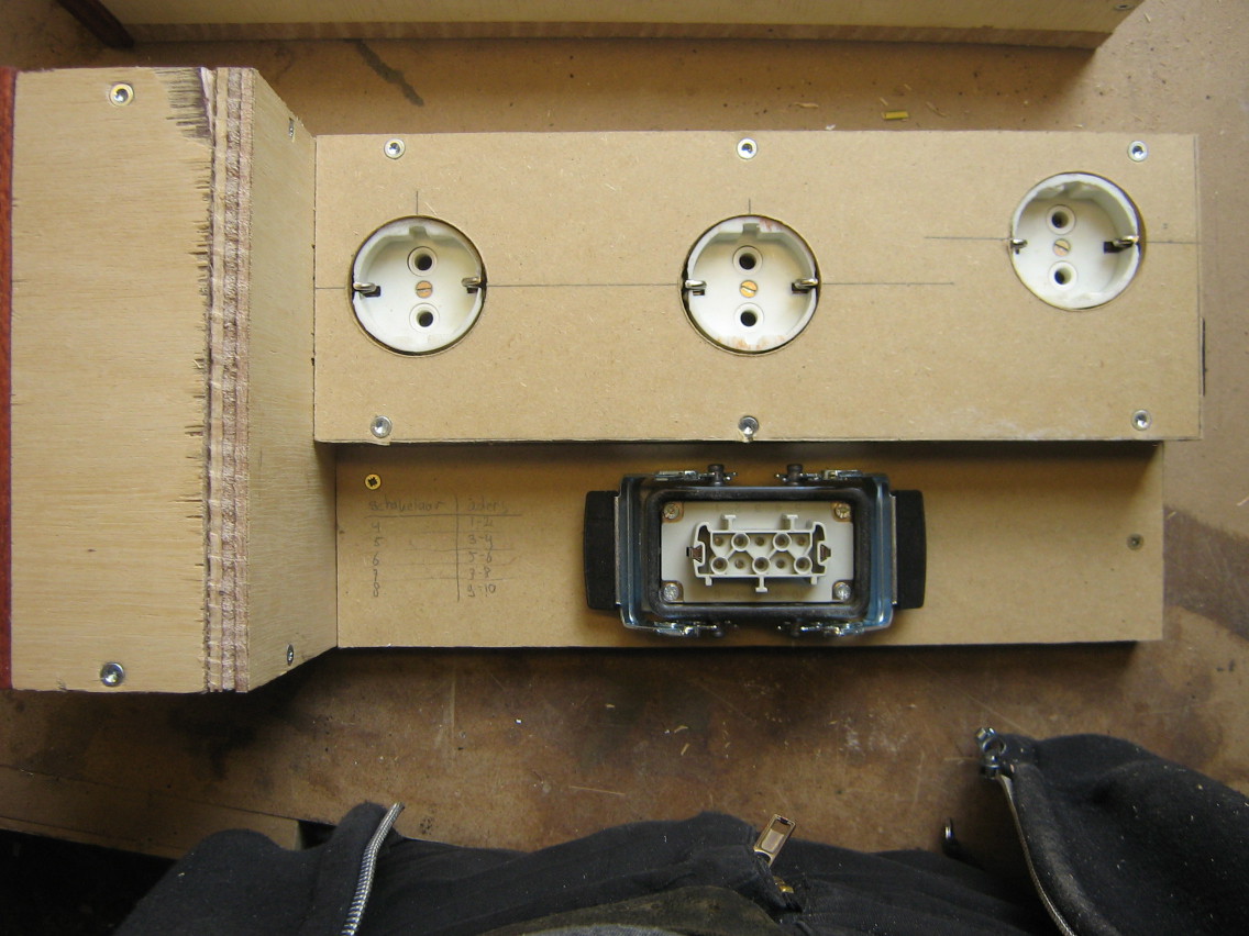
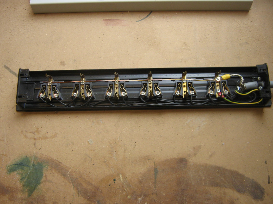
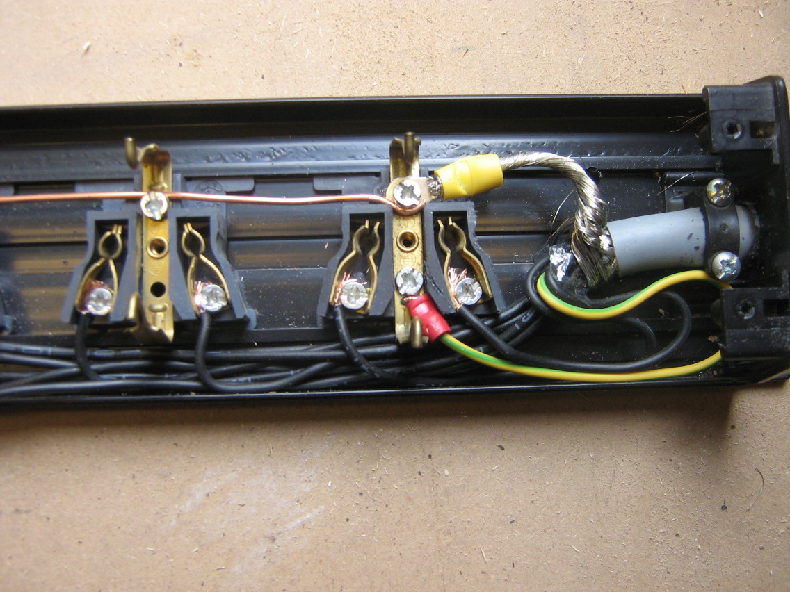
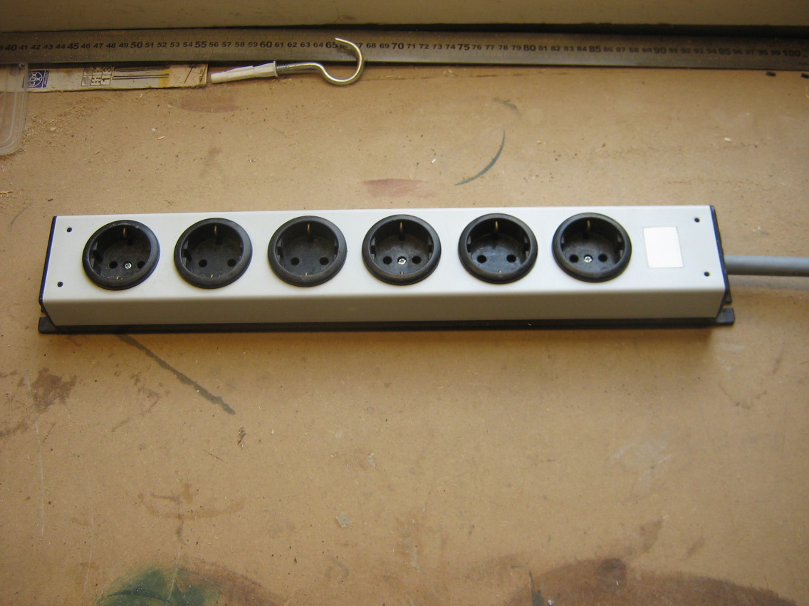
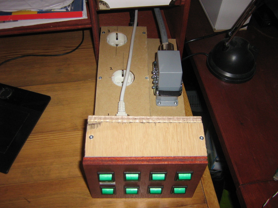
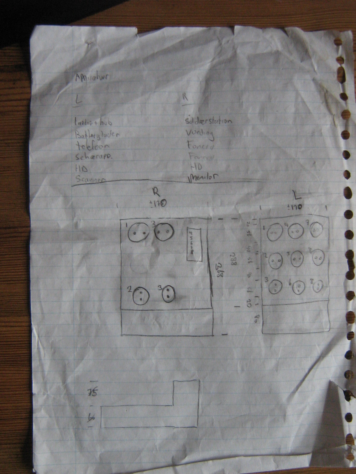
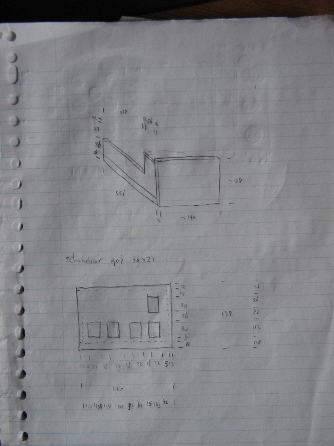
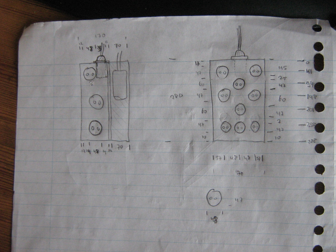
So, I ended up making five of the switches in the right panel control outlets in a separate power bar, which I put on my (second) desk instead of behind the panel. To be able to do this, I had to get a length of thick power cable containing 12 separate leads (two for each outlet, plus one for the earth terminal). Also, since I didn't want the cable to be fixed onto the switch box, I got a humongous power plug, containing 10 contacts (plus chassis earth).
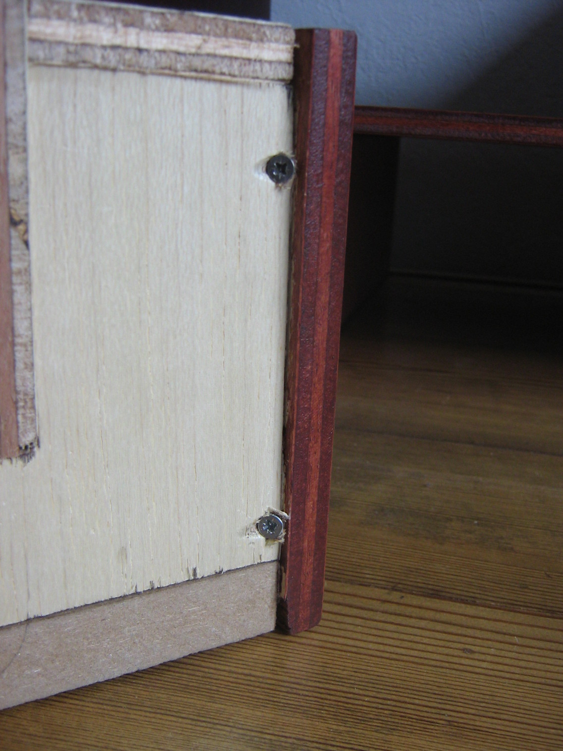
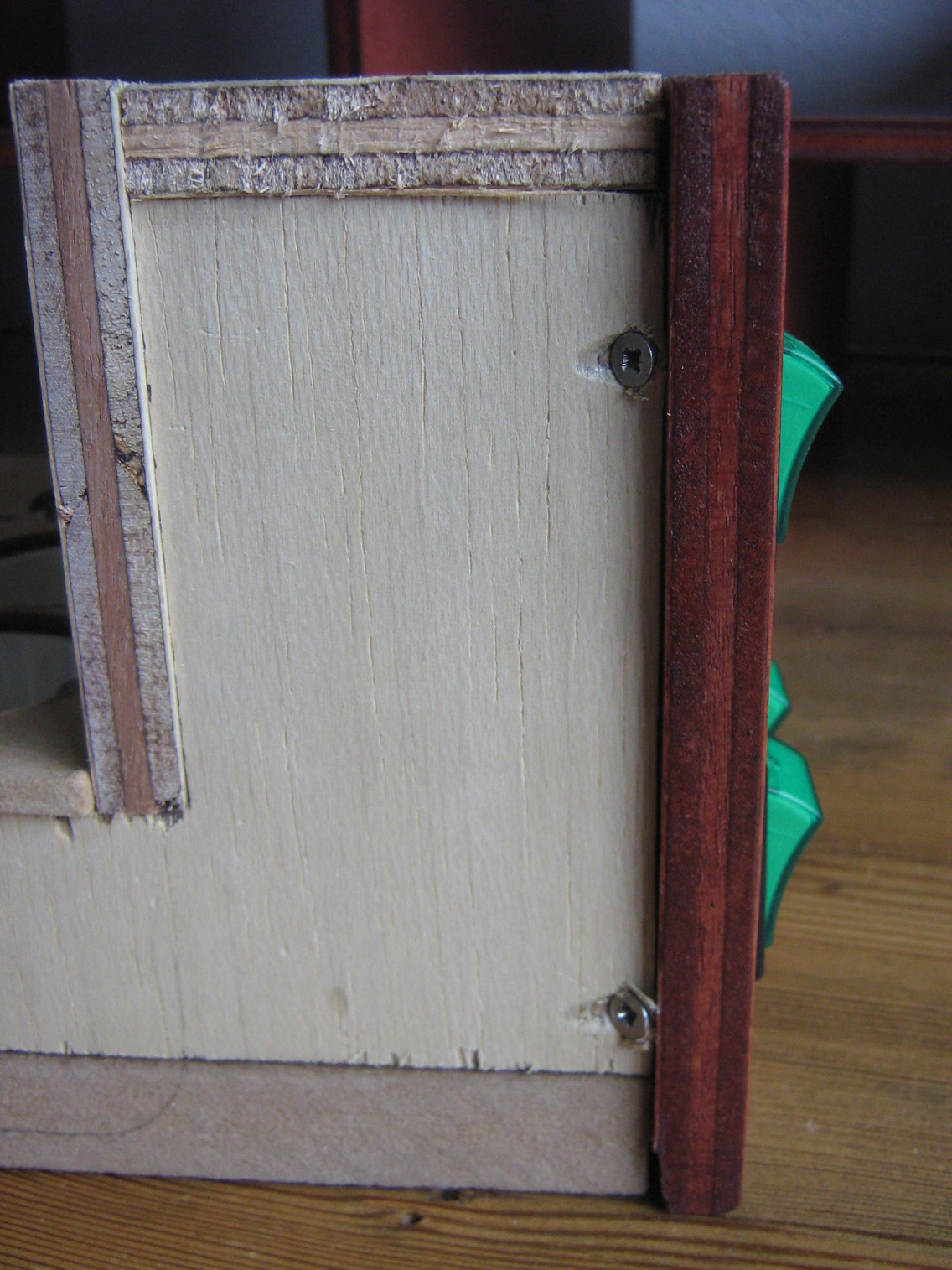
I designed these boxes for a current up to 10A. All components should be able to handle 16A, except for the power inlets, which contain a 10A fuse. Each switch panel contains 8 switches, for controlling 9 outlets (theres one switch in each box that controls two outlets).
I used two-pole switches, which can switch both the line and neutral terminals of each outlets. In theory, it should be sufficient to only switch the line terminals and leave the neutral terminals always connected, but since the boxes are connected to a wall socket using a normal power plug, there is no way to tell which incoming power wire is the line terminal and which is the neutral terminal, so you have to switch both of them.
One thing I had not accounted for in advance, is that the switch boxes themselves also draw a bit of power. The power inlets I used contain some filtering circuitry, which should improve the stability of the power delivered. However, these inlets also draw about 50-100mW (hard to measure since it's so little and has a low power factor) each, when there is nothing else connected. On yearly basis, this would amount to about one kWh, so that's not really a problem.
In addition, the lights in the switches also draw around 300mW, but since that only happens when a device is switched on, that power draw is negligible compared to the power usage of the connected device.
I started out building the cabinet, which took me just under a day (I just screwed all the panels together, not bothering with fine dovetail joints or other fine woodworking details, since I mostly wanted this cabinet to be functional without costing too much time. Then I started on the switch boxes, which took me three or four days in total, which seems really out of proportion :-)
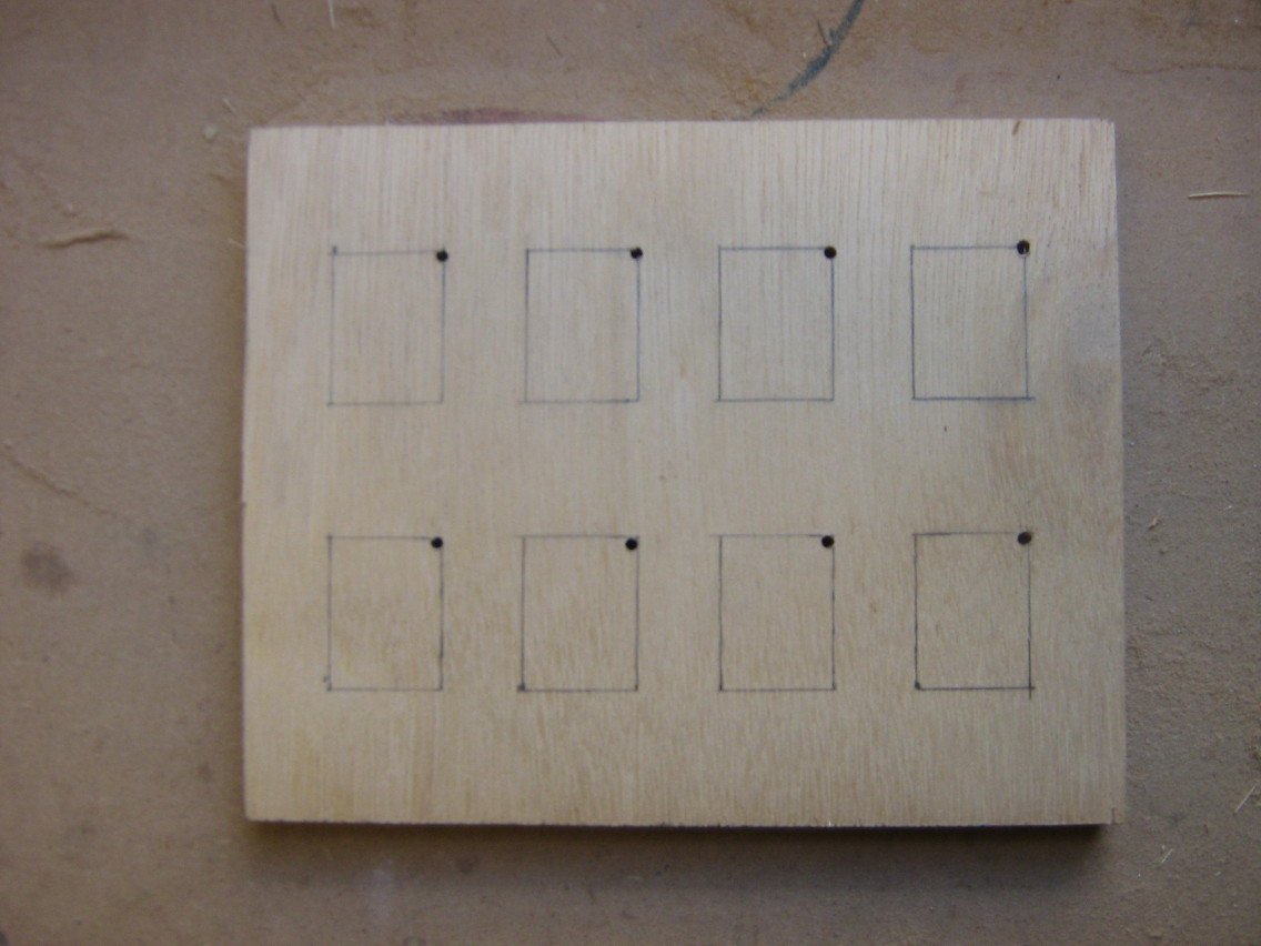
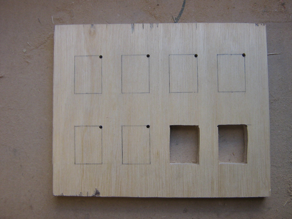
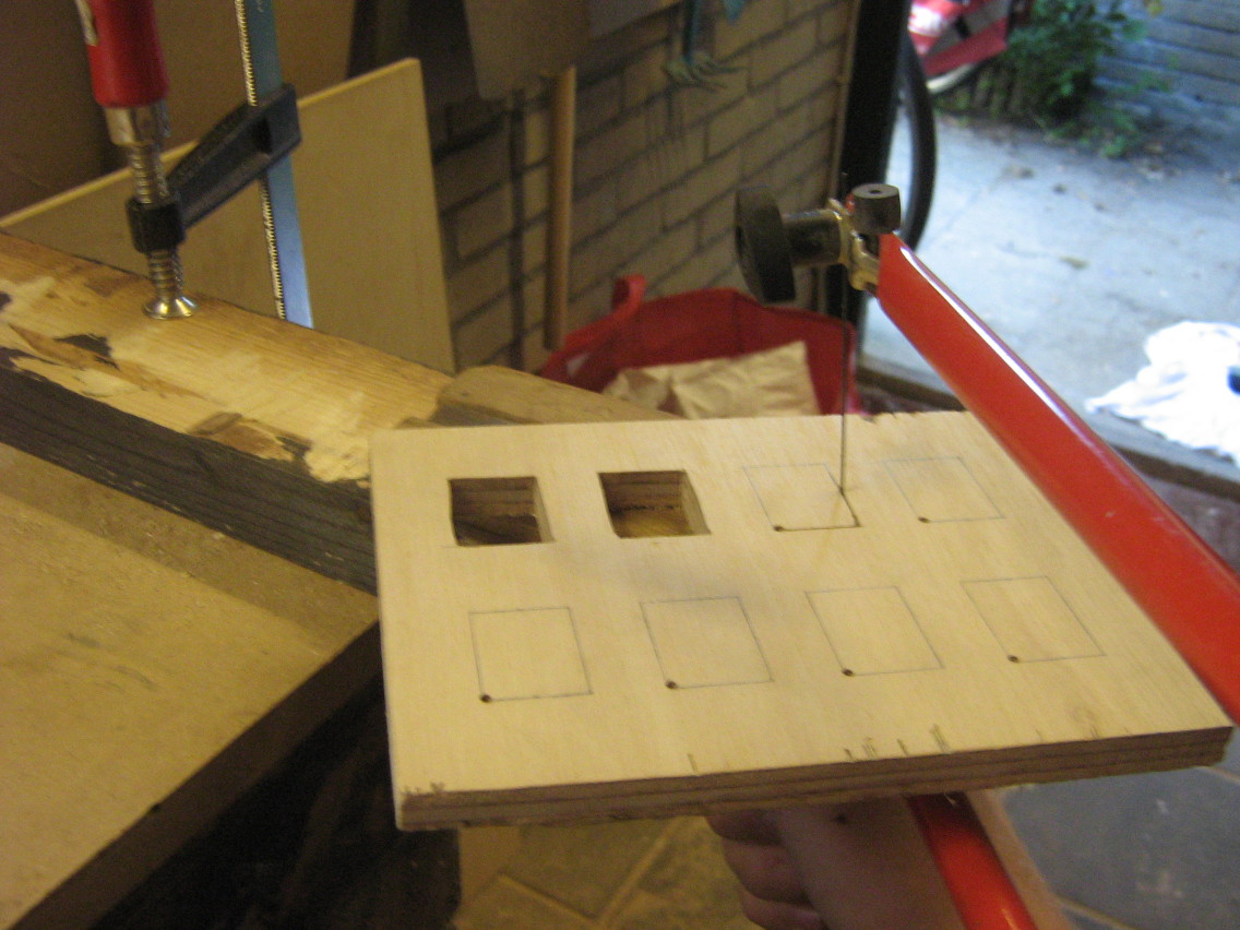
Front panels
I started out preparing the front panel, using an oldschool fretsaw. Fortunately, the switches have a small front panel that covers up a few milimeters of the hole, so I didn't have to get perfect cuts (though a few mm of space is still not that much room for error).
The switches are mounted in the panel by just snapping them into the holes cut out of the panel.
Outlets
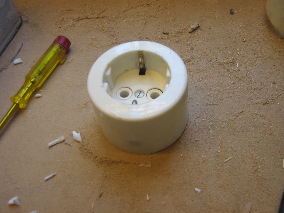
For the outlets, I was considering to use these power sockets or standard wall sockets, with the big downside of them being fairly expensive (± €8, I would need 20 of them). Fortunately, I found a box of old wall outlets at van Altena, local second-hand hardware store that has all kinds of old and new tools and equipment at cheap prieces. I ended up paying €0,75 per outlet, which reduced the total cost of the project quite a bit (though it still cost me around €175 in materials).
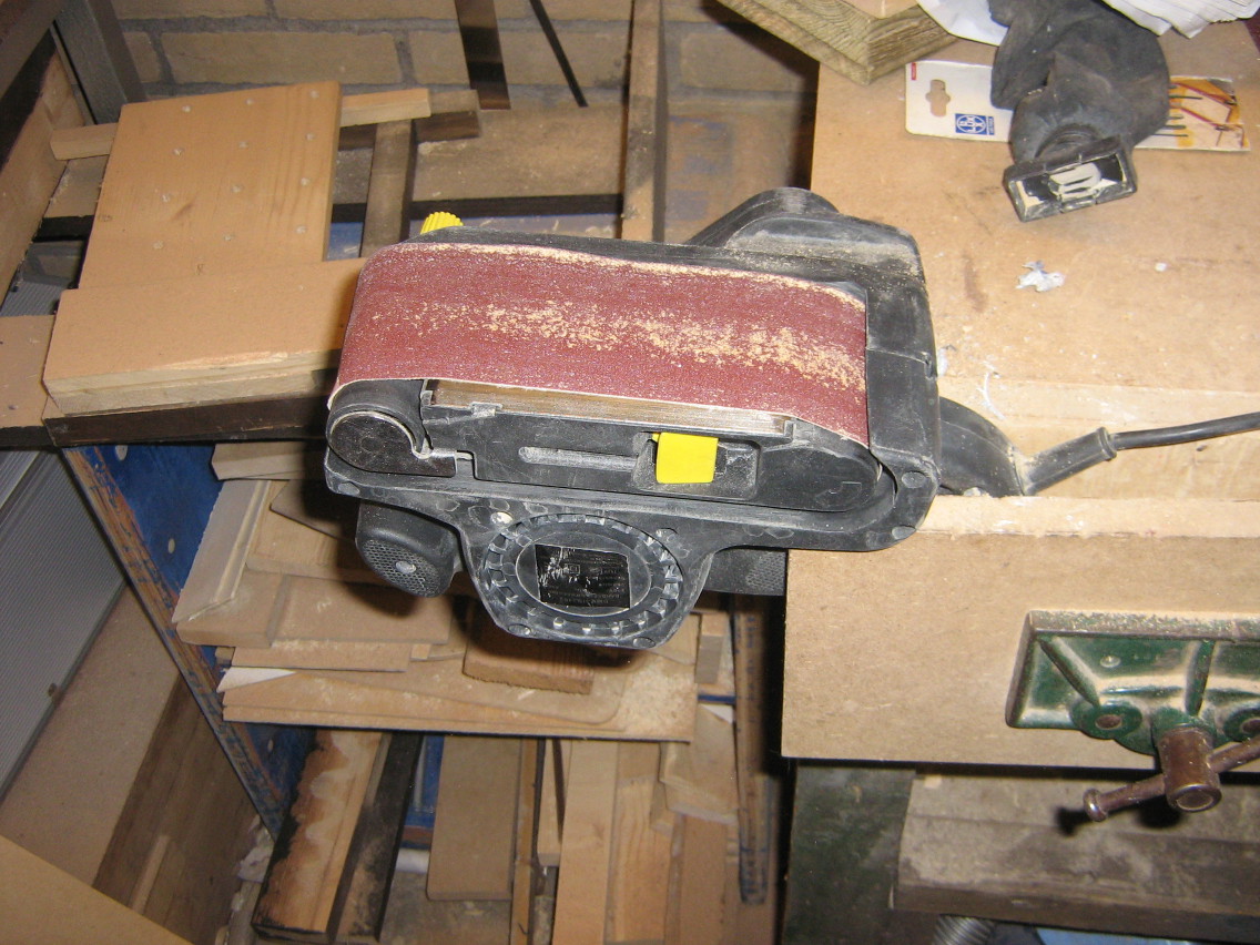
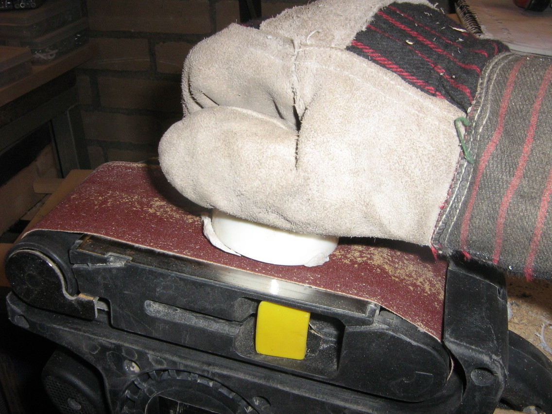
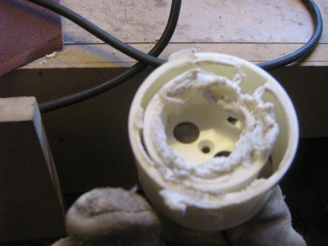
To save a bit of space and make everything fit better, I ended up cutting off the top of the outlets, so the outer mantle would come off and the outlets could be placed closer togeter. After doing the first one with a saw, I ended up doing all the others using a belt sander, fixed upside down in my vice creating an ad-hoc stationary belt sander.
Box construction
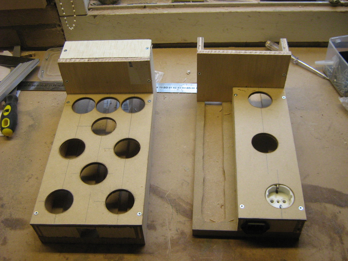
Next, I created a base for the boxes and constructed the boxes on top. Apparently I didn't take any pictures of the process (I remember doing so, but perhaps I somehow lost the pictures, not sure). The base plate is thick (18mm) MDF, on which I've used my router to route out a 10mm deep "trench" in the wood through which the cabling can be put (so it can go underneath the outlets). You can see one of the trenches on the left of the right box below.
Most of the rest of the construction is 15mm plywood, except for the top plate (with holes for the outlets), I used 6mm MDF for that.
Distribution wires
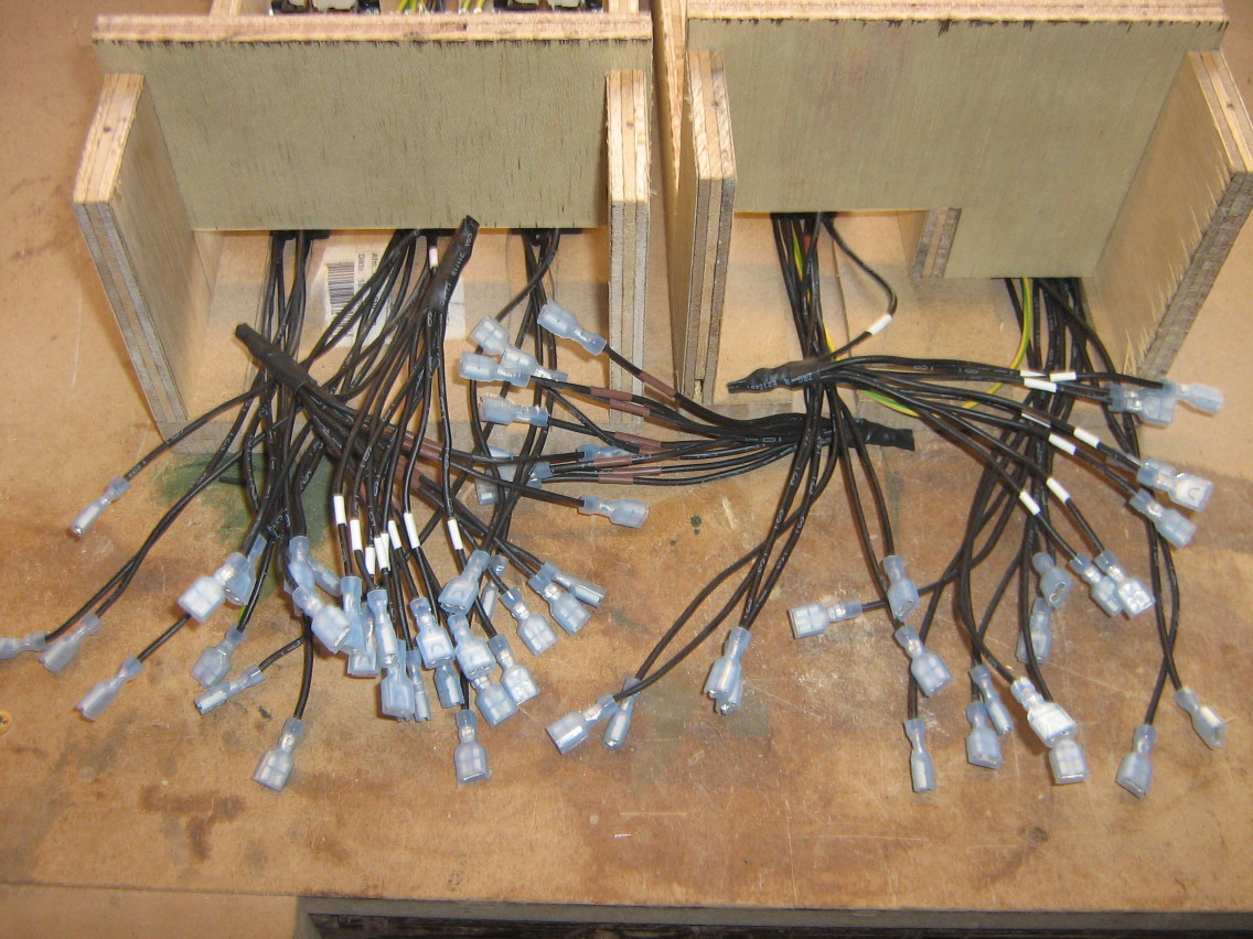
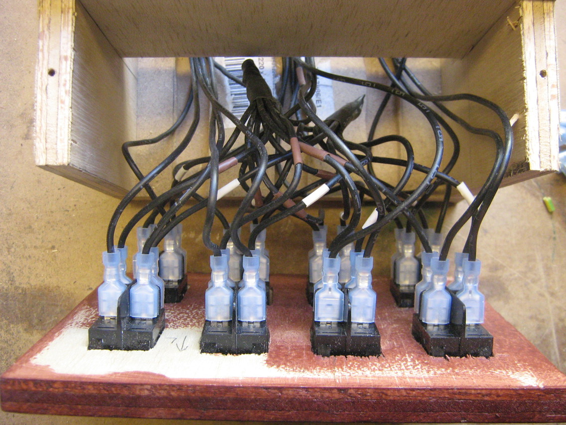
To connect the incoming power lines to each of the switches, I had a bit of a challenge. The switches have blade connectors, onto which blade receptacle connectors can be attached. These blade receptacles are "crimped" onto a cable. I tried to find some component that I could use to connect all a dozen of blade receptacles onto, but I couldn't find any of those. There are special blade connectors that allow daisy chaining each switch onto the next, but I didn't like the idea that the last switch would be connected through two dozen of crimp connections (and I did not have those daisy chaining connectors when I was working on this).
I also could not use a Twist-on wire connector, since that only works with solid cable (and the crimped blade connectors need stranded cable).
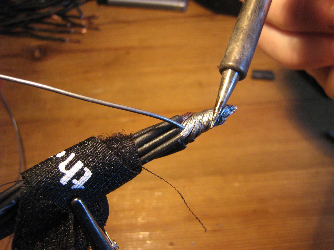
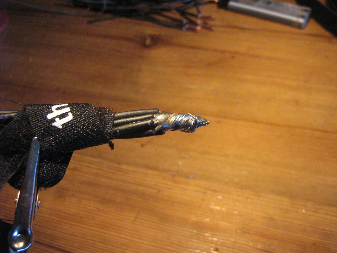
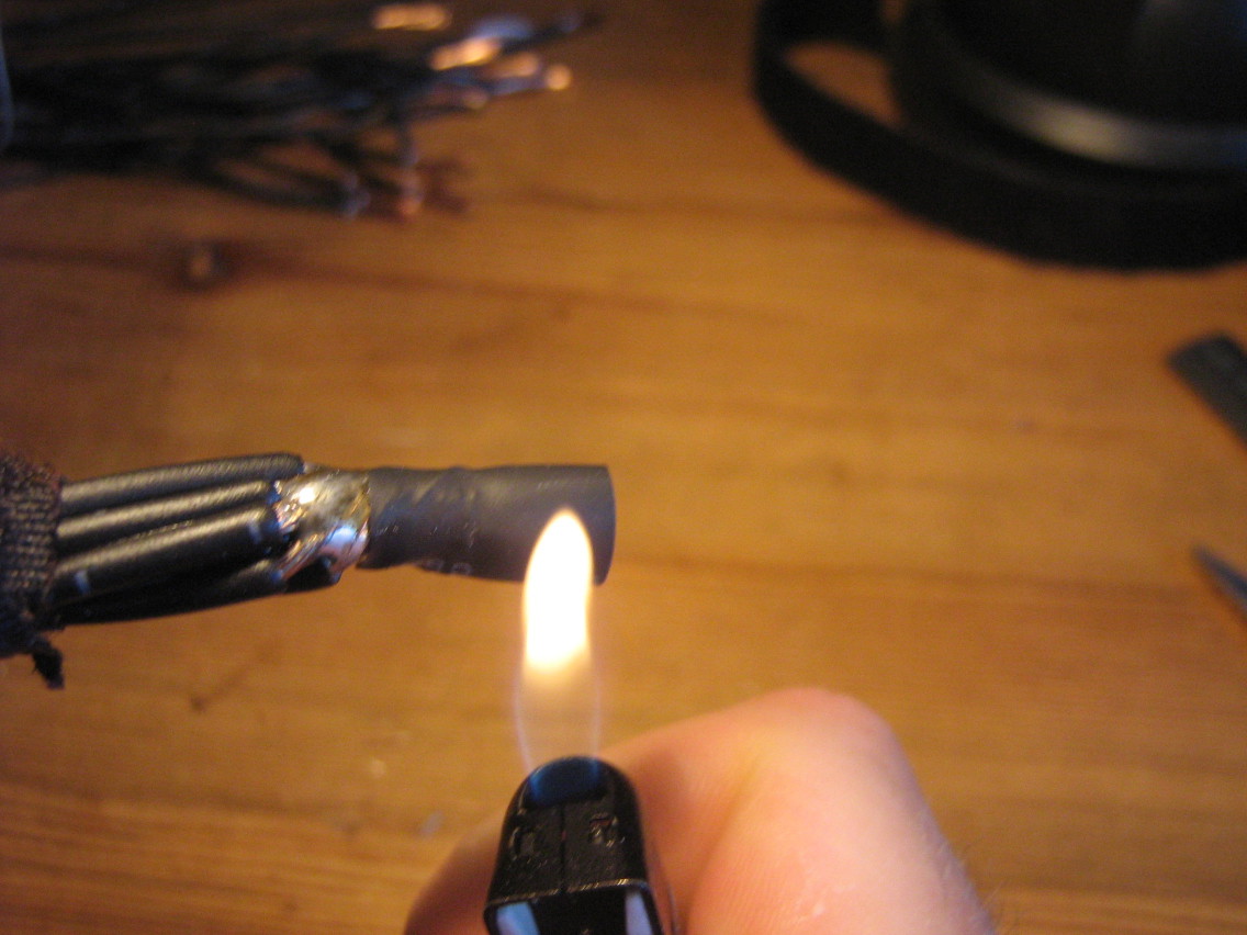
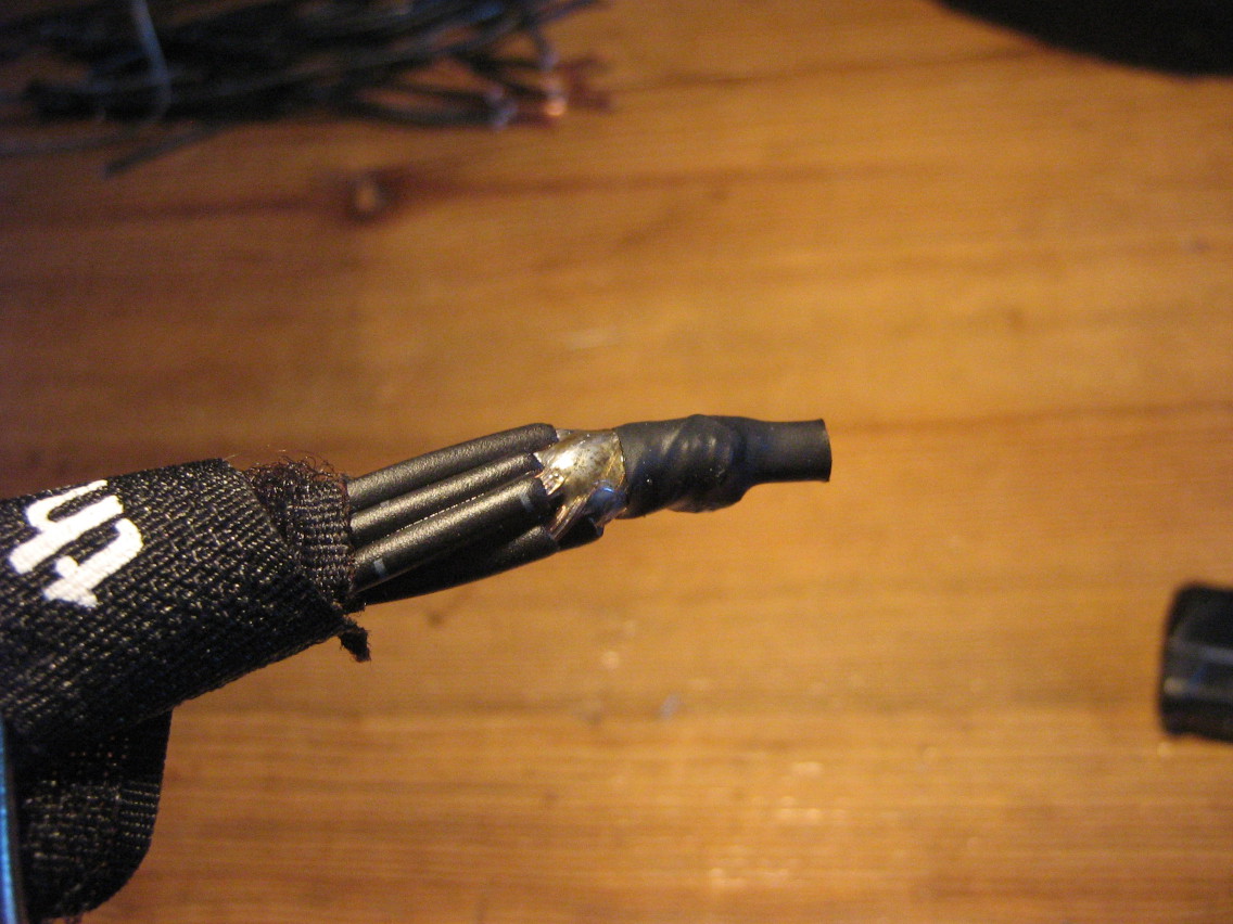
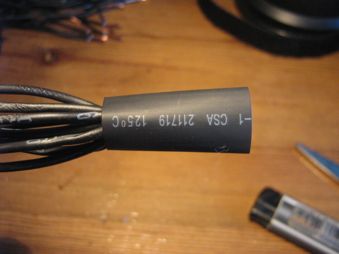
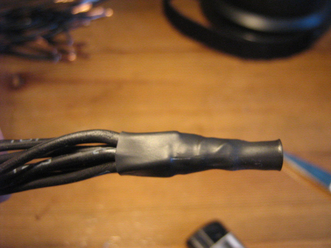
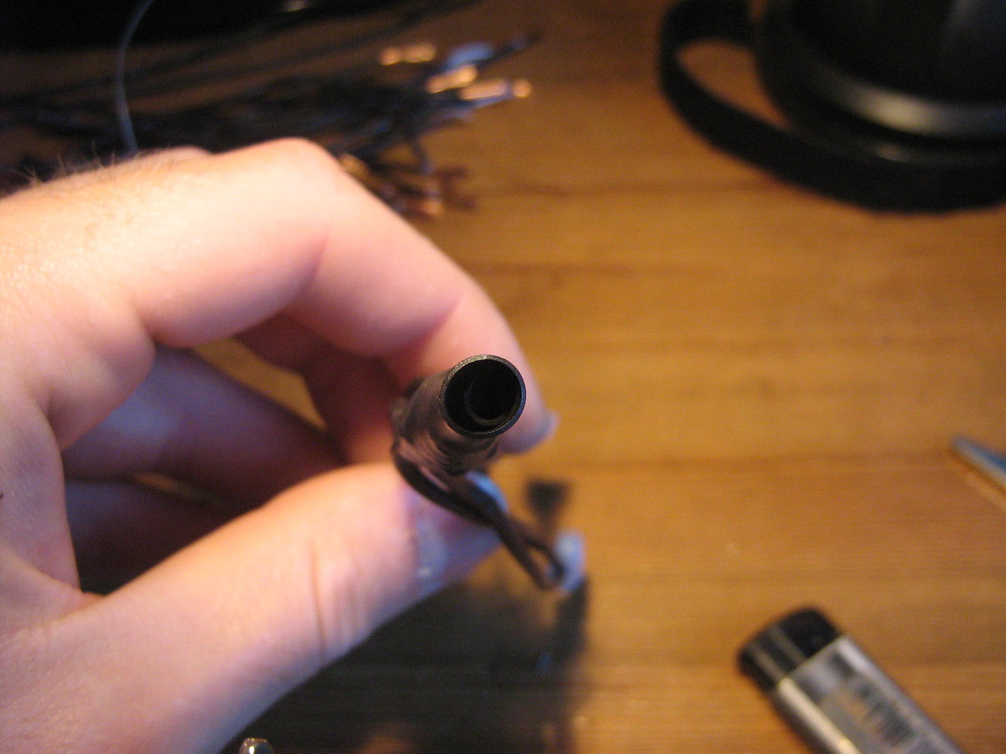
In the end, I just settled for soldering all these cables together. It's not very elegant, but I'm confident that this soldering connection should be capable of easily handling 16A of current, which is the most important in the end. I used two layers of heat-shrink tubing to insulate the big lump of soldering tin.
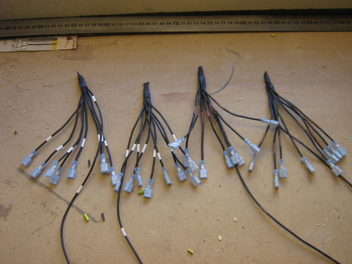
The last picture shows the end result: four cable octopusses that connect with one wire to the power entry point, and with eight wires to each of the switches. There's four of these in total, for both the line (with the brown marking tape) and neutral (with the white marking tape) connections in both of the boxes.
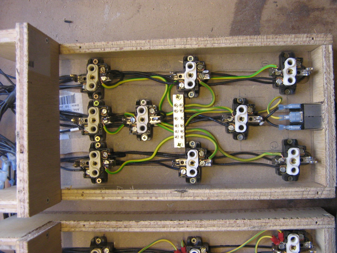
Connecting the outlets
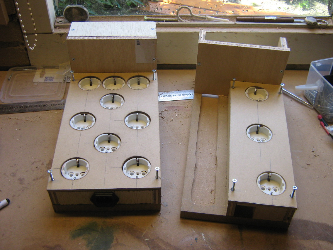
The line and neutral connections of each outlet need to be connected to a single switch. I first connected wires to all of the outlets, with a blade connector crimped onto the other side. I used wires cut from the multicable I bought, which are conveniently numbered. Since the line and neutral connections are interchangeable in the European outlet system ("Schuko"), I didn't need to add labels to distinguish both cables coming from the same outlet.
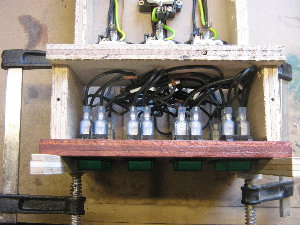
The earth terminals do not need to pass the switch, these need to be always connected. In the bigger box, I used an earthing terminal block (which is intended to be used in a breaker box) to connect the outlets in a "star" topology. For the smaller box, I couldn't find a smaller earthing terminal block, so I just daisy chained the outlets together. Since there's only a few outlets and there should never be much current through the earth terminals, this shouldn't be a problem here.
I also connected the multicable connector in the same way, but those wires are already covered by a MDF plate in the pictures.
The end result is 32 cables sticking out from each box, four cables for each switch.
Connecting the switches
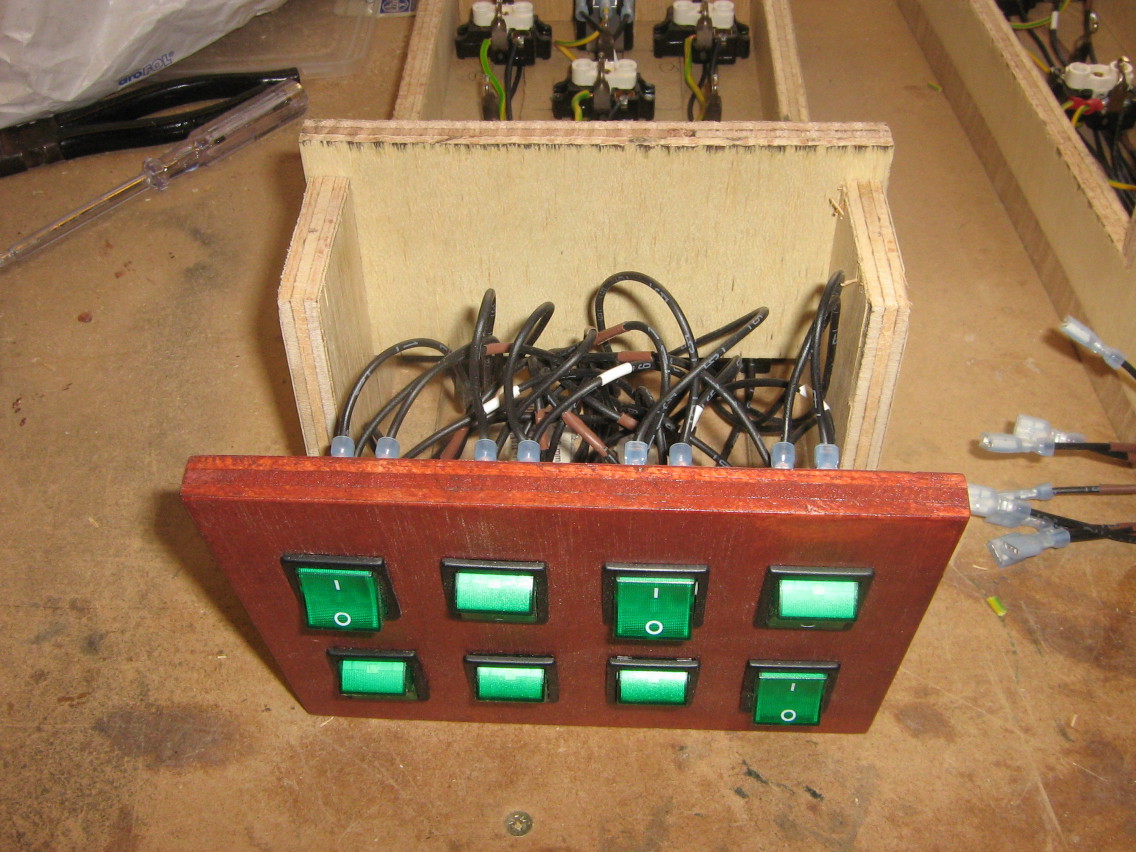
Connecting the switches was a matter of connecting all the 32 wires I prepared to the switches in the panel. After connecting the switches, I glued the front panel onto the box (so there would not be any visible screws on the front panel).
Assembled boxes
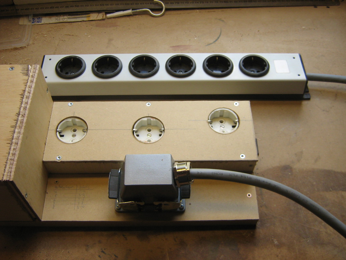
Now the boxes are assembled and ready for use, time to build the external outlet bar.
Note that the outlets seem a bit randomly placed, but I've tried to leave as much room available for power adapters to stick out in different directions, without blocking other outlets.
External outlets
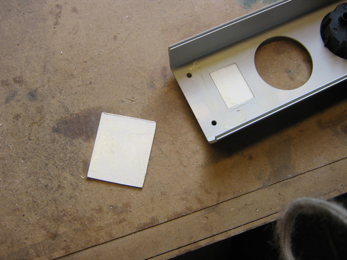
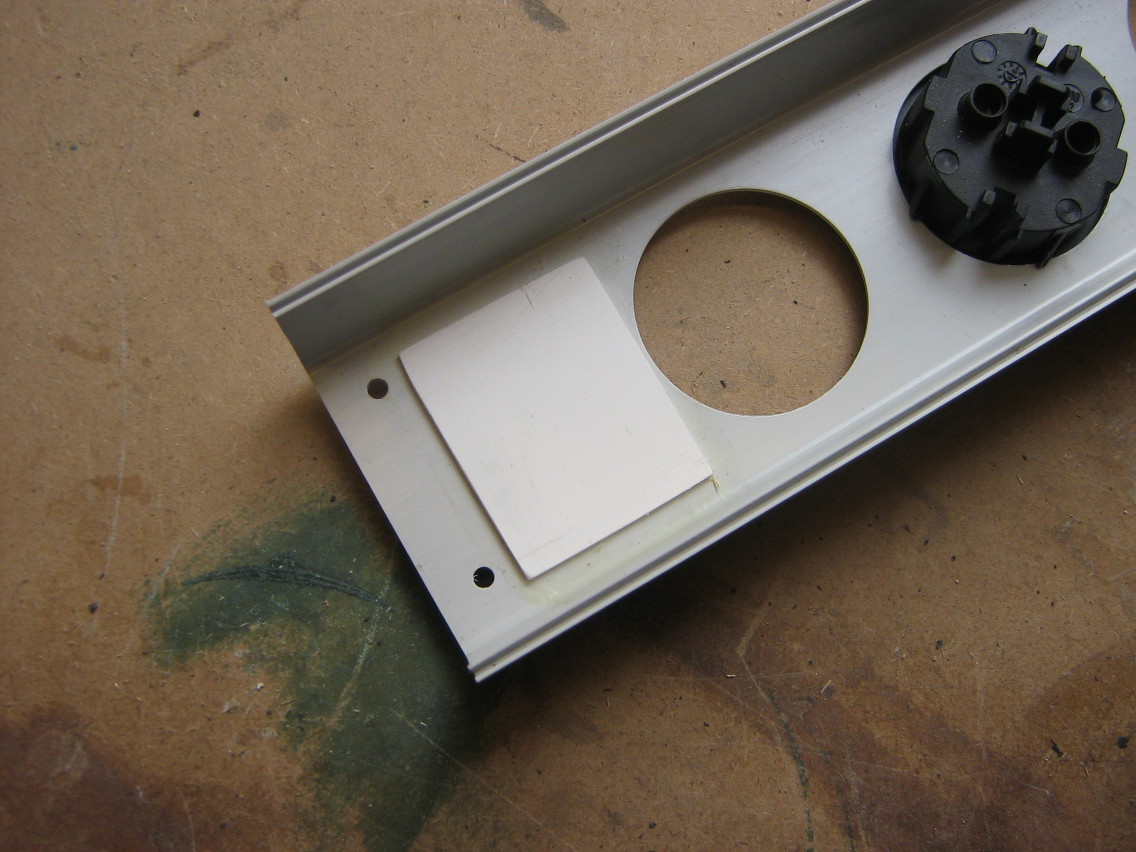
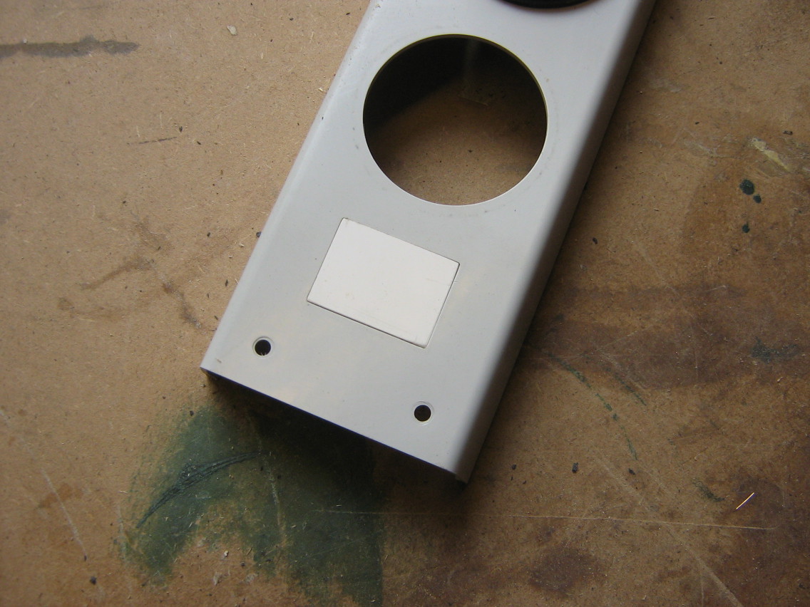
For the external outlets, I got an old powerbar (again at van Altena), which has each outlet individually connected internally. I connected the big multicable to all of the outlets on side and to the big connector on the other side of the cable
The old powerbar also had a single powerswitch to control all of the outlets. Since I couldn't find any use for this switch, I just removed it. To cover up the hole that it left, I used two rectangles cut out of an old plastic cable conduit. The smaller rectangle exactly fits in the hole, the larger rectangle just serves to glue the smaller one in place. The result is a cleanly covered switch hole.
Fixing the front panels
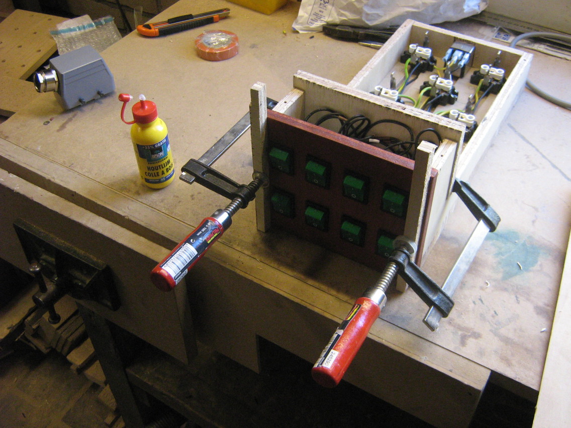
After installing the boxes into the cabinet, it turned out the front panels weren't glued on properly, the left one came off. Since I was already doubting if they would hold, I settled for a less elegant, but more secure solution: I just added some screws in an angle from the back, making them just long enough to not stick out at the front.
Finished
So, here's the finished thing. I really like the contrast between the green buttons and the red mahogany finish I used, it gives the thing a very classic look.
To be able to plug in devices, I can pull out the boxes towards the front. This is not very quick to do, but since I do not need to switch devices very often, that works out just fine.
I also added labels to the various switches, so I won't have to remember where I plugged in every device.
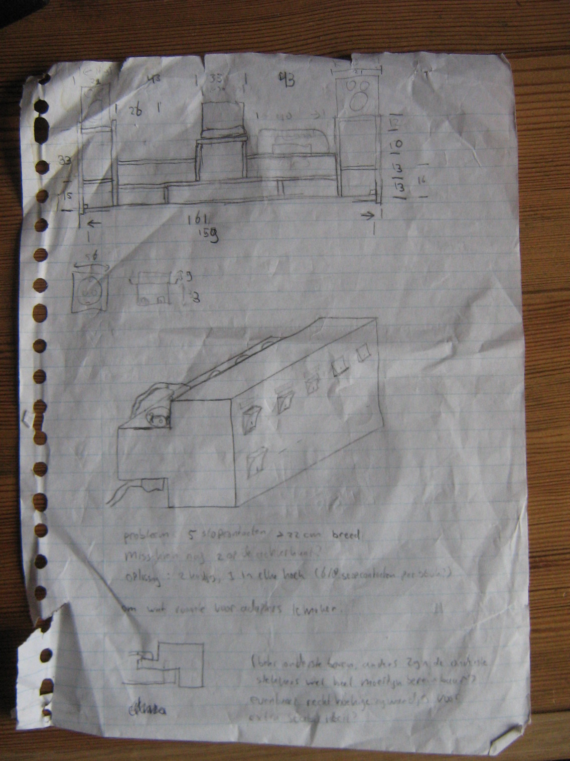
Design drawings
And just for historical reference, here are the design drawings I created during the process. If they look fuzzy to you, that's probably because I erased every part of the drawings probably at least once...

To be able to debug a bug in OpenTTD that only occured on SPARC machines, I needed an old SPARC machine so I could reproduce and hopefully fix the bug. After some inquiring at our local hackerspace, Bitlair (which had a few SPARC32 machines lying around, but I needed SPARC64), I got in touch with The_Niz from NURDSpace, the hackerspace in Wageningen. Surprisingly, it turned out I actually knew The_Niz already through work :-)
In any case, The_Niz was kind enough to lend me a SPARC Ultra1 workstation and Sun keyboard, and r3boot gave me a Sun monitor I could use (of course Sun hardware doesn't use a regular VGA connector...).
There was one caveat, though: The NVRAM battery in the Ultra1 was dead. The NVRAM chip stores the boot settings (like the BIOS settings in a regular PC), but also the serial number and MAC address of the machine (called the IDPROM info). Without those settings, you'll have to manually select the boot device on every boot (by typing commands at a prompt) and netbooting does not work, for lack of a MAC address (I presume regular networking, e.g., from within Linux, does not work either, but I haven't tested that yet).
Sun has taken an interesting approach to their NVRAM chip. Where most machines just use a piece of EEPROM (Flash) memory, which does not need power to remember its contents, Sun has used a piece of RAM memory (which needs power to remember its contents) combined with a small rechargeable battery.
This means that when the machine is not used for a
long time or is very old, the battery will eventually die, causing the
machine to spit out messages like "The IDPROM contents are
invalid and "Internal loopback test -- Did not receive expected
loopback packet".
I needed to install Debian on this Ultra1, so I needed some way to boot the installer. Since netbooting did not work, my first attempt was to ignore the NVRAM problem and just get the machine to boot off a Debian boot cd. This did not quite work out: the cdrom player in the Ultra1 (a 4x burner connected through SCSI) didn't like any of the CD-Rs and CD-RWs I threw at it. It spat out errors like "Illegal Instruction", "Program Terminated" or "SProgram Terminated" (where the first "S" is the start of "SILO", the SPARC bootloader).
As we all remember from a long time ago, the early generation CD-ROM players were quite picky with burnt CDs, so also this one. I found some advice online to burn my CDs at a lower speed (apparently the drive was rumoured to break on discs burned at 4x or higher), but my drive or CD-Rs didn't support writing slower than 8x... I could write my CD-RW at 4x and at one occasion I managed to boot the installer from a CD-RW and succesfully (but very, very slowly) scan the CD-RW contents, but then it broke with read errors when trying to actually load files from the CD-RW.
So, having no usable CD-ROM drive to boot from, I really had to get netboot going. Apparently it is possible (and even easy and not so expensive) to replace the NVRAM chip, but I didn't feel like waiting for one to be shipped. There is a FAQ available online with extensive documentation about the NVRAM chip and instructions on how to reprogram the IDPROM part with valid contents.
So, I reckoned that the battery was only needed when the machine was powered down, so I should be able to reprogram the IDPROM info and then just not poweroff the system, right?
Turns out that works perfectly. I reprogrammed the IDPROM using the MAC
address I read off the sticker on the NVRAM chip and made up a dummy
serial number. For some reason, the mkpl command did not work, I had
to use the more verbose mkp command. Afterwards, I gave the reset
command and the "Internal loopback test" error was gone and the machine
started netbooting, using RARP and TFTP.
By now, I've managed to install Debian, get Xorg working and reproduce the bug in OpenTTD, so time for fixing it :-D

Recently, I was having some problems with the internal speakers on my Lenovo Thinkpad X201. Three times now, the internal speakers just stopped producing sound. The headphone jack worked, it's just the speakers which were silent. Nothing helped: fiddling with volume controls, reloading alsa modules, rebooting my laptop, nothing fixed the sound...
When trying to see if the speakers weren't physically broken, I discovered that booting into Windows actually fixed the problem and restored the sound from the speakers. It's of course a bit of a defeat to accept Windows a fix for my problem, but I was busy with other things, so it sufficed for a while.
When migrating my laptop to my new Intel SSD, I broke my Windows installation, so when the problem occured again, I had no choice but to actualy investigate it.
I'll skip right to the conclusion here: I had broken my sound by pressing the mute button on my keyboard... Now, before you think I'm stupid, I had of course checked my volume controls and the device really was unmuted! But it turns out the mute button in Thinkpads combined with Linux is a bit weird...
This is how you would expect a mute button to be implemented: You press the mute button, it sends a keypress to the operating system, which then tells the audio driver to mute.

This is how it works on my Thinkpad: You press the mute button, causing
the EC (embedded controller) in the thinkpad to directly mute the
speakers. This is not visible from the normal volume
controls in the software, since it happens on a very low level (though
the thinkpad_acpi kernel module can be used to expose this special
mute state through a /proc interface and special audio device).
In addition to muting the speakers, it also sends a MUTE acpi keypress
to the operating system. This keypress then causes the audio driver to
mute the audio stream (actually, it's pulseaudio that does that).
Now, here's the fun part: If you now unmute the audio stream through the software volume controls, everything looks like it should work, but the hardware is still muted! It never occured to me to press the mute button again, since the volume wasn't muted (or at least didn't look like it).
I originally thought that the mute button handling was even more complex, when I found some register polling code that faked keypresses, but it seems that's only for older Thinkpads (phew!).
In any case, the bottom line is: If you have a Thinkpad whose speakers suddely stop working, try pressing the mute button!

After nearly five years of intensive use, the time has finally come to replace my trusty S270 laptop, Xanthe. Overall, I'm surprised that she held out as long as she did. There has been some defects along the way, but in the end I've managed to keep things pretty much working (where the most recent and most serious fix was to remove the laptop speakers and soldering the inverter cable, which got partly severed in the screen hinge).
However, since a few months, there is one issue that I can't seem to fix: The AC adapter plug doesn't seem to properly connect to the socket, making the battery switch between charging and not charging all the time (once per second or so). This had a great number of side effects, like keys on my keyboard getting stuck or making the keyboard stop working completely, making my network connection break, making my screen brightness change eratically and other stuff that makes me utterly and completely annoyed. I've made a detailed post on the s270-linux mailing list about that, if you're interested.
So, after a few months of on-and-off annoyance, I've finally decided to get a new laptop. It's sucky, since apart from this issue, Xanthe is still serving me well. On the other hand, it's utterly cool, since I just ordered myself a Thinkpad X201. It's a very durable and efficient 12" notebook (over 10 hours of battery life, according to Lenovo!). More details when I get the package (should be somewhere this week!).
Recently I've been fixing up some critical defects in my MSI S270 notebook: My display stopped working due to a broken inverter cable and my power adapter switched on and off all the time due to a broken cable as well.
The inverter cable goes from the laptop mainboard to the inverter, which is below the display. On its way it passes the left hinge, which is exactly where it was broken. Apparently I'm not the only one having these kinds of problems with the S270. Some people suggest that the hinges are badly made causing these problems.
I've looked closely at the inverter cable and it even seems the cable breaks are caused by a tiny thread that is wrapped around the inverter cable to keep it together. Three of the six (IIRC) wires has broken and a few more had cuts in the insulation. The breaks were very clean and seemed to be exactly at the spot where the wrapping thread had cut into the insulation...
Anyway, I managed to solder the tiny wires back together again (using some extra wire to fill the gap). The cable did become bigger from this, so I had to remove the speakers and their cable to make a bit room in the hinge to fit the soldered cable in.

It has been working for a few weeks now, but I'm afraid the solder connection will break eventually again. In the meanwhile I've been trying to get a new cable, but it's pretty impossible to get at and MSI Netherlands refuses to sell me a cable. They say the want to use all cables they have for repairs, meaning I have to send my entire laptop to them and pay €80 - €150 for a repair I could have done myself (the part alone is usually €20 - €30...).
I'm still happy with the laptop, while it is working, but I won't be buying another MSI when this one finally breaks down for good...
My power adapter cable had also broken, switching on and off when I wiggled with the cable. The cable used to have two round "blocks" at the start and the end (ferrite rings to prevent interference). Over a year ago the cable broke near one, now it broke near the other one. I've removed both of them now and soldered the stuff back together, making it work again.
With no indication as to why, the battery light of my laptop started blinking red yesterday. Normally it is green when charging, red when nearly empty and off otherwise. It shouldn't be blinking, ever. But it did.
Turning off the laptop, reinserting the battery, leaving it out for a while, none of this helped to stop the light from blinking. Some closer inspection showed that when not connected to AC power, the battery was discharging and Linux could read out the status just fine. However, when connected to AC power, the battery would not charge, and the status would be "unknown"!
I tried swapping the battery with my old one, which worked just fine. This seemed to suggest that my battery had somehow got broken. Since I've only bought the battery a few months back, I was already dreading having to deal with MSI support yet again. To confirm that the problem was in fact with the battery and not my laptop, I put my battery in Brenda's laptop (who has the highly similar S271). There, it worked like it should, giving a fancy green light. However, when I put the battery back into my own laptop, all the problems were gone and it charged normally again...
I'm still not completely sure what happened, but it seems like the battery got into some state that my S270 couldn't fix, but the newer S271 perhaps could? Oh well, glad it's working again, now let's hope it won't break again...
As you might have read in my previous post, I have been vastly unimpressed by MSI's warranty department. Or actually, I have been actually been quite impressed by the amount of incompetence that they have managed to concentrate in that department. But, I digress.
A few weeks back, MSI managed to take weeks to not replace my hard drive. I have been complaining about this, and they offered that I sent them the faulty drive (again) so they could replace it. Yet they could not send me a new drive, before they had received the old drive, since "the system would not allow it". They would not, however, require me to send back my entire notebook again, as a courtesy. It's not like I could use it for anything but decoration without a hard drive (it does not support booting from an USB stick, I discovered after installing debian om my stick), but well.
I was going to write a nice piece about MSI support here, as soon as I got my notebook back from MSI. About their nice service (pick up and return with UPS!) even though they are a little slow-ish. About their nice battery warranty (minimal 80% of capacity after a year) and their flexibility in applying that warranty (I was a few days too late, technically) But, I've decided not too.
There are several reasons for this. First of all, my notebook HD broke in the first place. Not a nice thing to do, though I should probably blame WD for not making HD's that can sustain repeated writes resulting from hibernation in the same area of the disk.
It could also be because it took them nearly a week to respond to my service request when I complained about a bad HD (with complete smart status and error logs to back up my case). All I got back was a UPS label, but I reckoned it took them a while to fully read through my case and decide what to do with it. As it turns out now, it seems they didn't even read it and just needed 6 days to send me a UPS label.
For the last couple of months, I've been having issues with my Linux hibernation. I had it working from the start, but for some unknown reason, it ceased working as of kernel 2.6.16. For the past months I have been unable to upgrade my kernel, since I did not have enough time to find and solve the problem.
This was nasty, since the newer versions of my wireless network drivers require > 2.6.16, the wacom tablet drivers have a few new features in 2.6.18 and there should be support for my (built-in) SD card reader since 2.6.18 (really generic support for SD host controllers ). None of which I could use, since upgrading would break my hibernation (and I really can't use my notebook without hibernation).
Last week, 2.6.19 was released. Even though I couldn't find anything in the changelog that would fix my hibernation (I'm nearly done reading it), I decided to give it a try anyway. Well, waddayaknow? It worked right away! I have to admit that suspend and resume is slower than it used to be (5s vs 2s for the actual writing/reading to/from disk), but it at least it works.
Also, the generic SD card reader support worked straight away, despite a warning in my kernel log:
sdhci:slot0: Unknown controller version (16). You may experience problems.
So far, I've not experienced any problems, though I haven't really done any real testing yet...
Another weird side effect of this new kernel is the occurrence of APIC errors:
APIC error on CPU0: 40(40)
So far, there have been no ill effects apart from this message, so I'll just ignore it for now. It is typical however, that I get this error roughly every 1000 seconds. Oh well...
As an added bonus, 2.6.19 introduces "MSI laptop extras". This allows me to query the state of my WLAN/Bluetooth button and allows my to set the display brightness programmatically. Real nifty, though I'm not sure how to use it just yet...
Update: It seems that suspend code now no longer swaps out applications before writing the memory to disk. This means the actual writing takes longer but starts earlier. In particular it also means that after desuspending, I don't have to wait until firefox gets unswapped first.
Recently, I've added an extra memory module to xanthe, my notebook. Originally, she shipped with 512 MB DDR400 (== 200Mhz) memory. I added 1024 MB DDR400. For some weird reason, this caused my memory to be clocked at 133Mhz instead of 200Mhz, even when both memory modules support 200Mhz. Removing either memory module makes the other module at 200Mhz again.
Tonight I was googling around for a fix for this problem, when I found that a new BIOS version was released (v6.70, while I was running v6.50). Since MSI does not seem to like changelogs, my only option was to just try. Easier said then done, since the supplied flash program needs dos to run. The recommended way for this is, as usual, "Make a dos bootable floppy and run the program". Not having a floppy drive severely limited my options here. So, I googled around and found the "ultimate boot cd", wich should be able to boot into DOS.
Trying the UBC (supplied as a 200M iso download) proved very handy. It provides a FreeDos and OpenDos installation (IIRC, the flash tool worked under OpenDOS, but not FreeDOS). Furthermore, a lot of testing utilities and hard drive tools are included on the CD. Nice to have lying around.
Anyway, updating the bios was succesful (though my laptop did a full powerdown when it was finished, I suspect this was a feature of the flash tool). I was unable to see directly if it also solved my problem, since the new BIOS does not show the memory speed anymore (which would be a very stupid way to 'fix' the problem). But, using Memtest86+ (also on the UBC), I found out my memory was correctly clocked at 200Mhz.
Dehibernating my linux worked, which I did not really expect and I experienced a significant speedup when dehibernating and especially deswapping Firefox. Yay!
Lastly, when I first bought my notebook, I promised to post pictures of her insides and a tutorial on dissassembling the S270. Just now, I've found a S270 disassembling guide by MSI themselves, so I won't bother anymore. I might publish the pictures anyway if I finally get my gallery plugin to properly work.