These are the ramblings of Matthijs Kooijman, concerning the software he hacks on, hobbies he has and occasionally his personal life.
Most content on this site is licensed under the WTFPL, version 2 (details).
Questions? Praise? Blame? Feel free to contact me.
My old blog (pre-2006) is also still available.
See also my Mastodon page.
| Sun | Mon | Tue | Wed | Thu | Fri | Sat |
|---|---|---|---|---|---|---|
| 1 | 2 | 3 | 4 | 5 | 6 | |
| 7 | 8 | 9 | 10 | 11 | 12 | 13 |
| 14 | 15 | 16 | 17 | 18 | 19 | 20 |
| 21 | 22 | 23 | 24 | 25 | 26 | 27 |
| 28 | 29 | 30 | 31 |
(...), Arduino, AVR, BaRef, Blosxom, Book, Busy, C++, Charity, Debian, Electronics, Examination, Firefox, Flash, Framework, FreeBSD, Gnome, Hardware, Inter-Actief, IRC, JTAG, LARP, Layout, Linux, Madness, Mail, Math, MS-1013, Mutt, Nerd, Notebook, Optimization, Personal, Plugins, Protocol, QEMU, Random, Rant, Repair, S270, Sailing, Samba, Sanquin, Script, Sleep, Software, SSH, Study, Supermicro, Symbols, Tika, Travel, Trivia, USB, Windows, Work, X201, Xanthe, XBee
 &
&
(With plugins: config, extensionless, hide, tagging, Markdown, macros, breadcrumbs, calendar, directorybrowse, entries_index, feedback, flavourdir, include, interpolate_fancy, listplugins, menu, pagetype, preview, seemore, storynum, storytitle, writeback_recent, moreentries)
Valid XHTML 1.0 Strict & CSS
Since ages, I've been using switched power bars to connect my computer equipment. Originally, I used a normal outlet to connect my PC and a switched bar to connect my monitor, speakers, printer, etc. This allows me to actually completely switch off everything when I'm not using it, saving a couple of Watts of leakage power and removing the need to switch all of my equipment off separately.
Since then, the amount of electrical stuff on my desk has increased a bit, now also including quite some stuff unrelated to my computer. I now count: a laptop adapter, an USB hub, speakers, a printer/scanner, an external hard disk, a battery charger, a phone charger, a charger for my shaver, some soldering equipment, a pile of wireless access points (my work for Fon).
Plugging in all this stuff in a single power bar wasn't very helpful: I would have the bar turned on most of the day when working on my laptop, so all the other devices would be leaking power as well.
It thought I found the perfect solution when I found this power bar with five individually switched outlets from Brennenstuhl. However, because both the switches and the outlets need some space, this power bar is pretty huge (±60 cm long), making it pretty impossible to give it a useful place on my desk (without taking up too much desk space), so I would have to think of something else.
I have been thinking about building a nice cabinet to put on top of my desk to put my laptop, speakers and printer on top of and to put various paperwork and other misc items in (to replace the cardboard boxes that kept my laptop at an ergonomical height until then). In the design of that cabinet, I realized that I could just as well include some power switch panels in the cabinet.
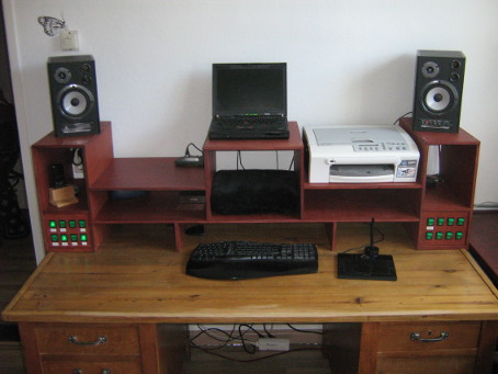
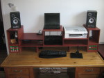
After a few iterations of the design, I ended up with the following result:
As you can see, there's two switch panels with eight switches each in the lower corners. Each switch controls one or two outlets, most of which are hidden behind the panels. Since most of the devices don't move around much, it's perfect if the outlets and plugs are hidden inside the cabinet, since that means less cluttering of my desk.
However, I also have some devices (mostly wireless access points, settopboxes and monitors that I use for my work) that are not fixed all the time and regularly change. If I would need to get behind the switch panels everytime I wanted to change a device, I would get tired of that real quick. I could of course have used a completely separate outlet bar for those devices, but I still like to make those devices individually switched (since most of them have power adapters, which are prone to leak power, and I hardly ever use all of the devices at the same time).
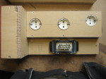
So, I ended up making five of the switches in the right panel control outlets in a separate power bar, which I put on my (second) desk instead of behind the panel. To be able to do this, I had to get a length of thick power cable containing 12 separate leads (two for each outlet, plus one for the earth terminal). Also, since I didn't want the cable to be fixed onto the switch box, I got a humongous power plug, containing 10 contacts (plus chassis earth).
I designed these boxes for a current up to 10A. All components should be able to handle 16A, except for the power inlets, which contain a 10A fuse. Each switch panel contains 8 switches, for controlling 9 outlets (theres one switch in each box that controls two outlets).
I used two-pole switches, which can switch both the line and neutral terminals of each outlets. In theory, it should be sufficient to only switch the line terminals and leave the neutral terminals always connected, but since the boxes are connected to a wall socket using a normal power plug, there is no way to tell which incoming power wire is the line terminal and which is the neutral terminal, so you have to switch both of them.
One thing I had not accounted for in advance, is that the switch boxes themselves also draw a bit of power. The power inlets I used contain some filtering circuitry, which should improve the stability of the power delivered. However, these inlets also draw about 50-100mW (hard to measure since it's so little and has a low power factor) each, when there is nothing else connected. On yearly basis, this would amount to about one kWh, so that's not really a problem.
In addition, the lights in the switches also draw around 300mW, but since that only happens when a device is switched on, that power draw is negligible compared to the power usage of the connected device.
I started out building the cabinet, which took me just under a day (I just screwed all the panels together, not bothering with fine dovetail joints or other fine woodworking details, since I mostly wanted this cabinet to be functional without costing too much time. Then I started on the switch boxes, which took me three or four days in total, which seems really out of proportion :-)
Front panels
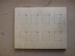
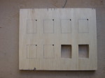
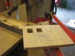
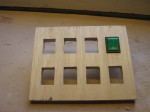
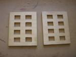
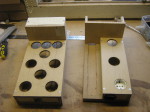
I started out preparing the front panel, using an oldschool fretsaw. Fortunately, the switches have a small front panel that covers up a few milimeters of the hole, so I didn't have to get perfect cuts (though a few mm of space is still not that much room for error).
The switches are mounted in the panel by just snapping them into the holes cut out of the panel.
Outlets
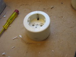
For the outlets, I was considering to use these power sockets or standard wall sockets, with the big downside of them being fairly expensive (± €8, I would need 20 of them). Fortunately, I found a box of old wall outlets at van Altena, local second-hand hardware store that has all kinds of old and new tools and equipment at cheap prieces. I ended up paying €0,75 per outlet, which reduced the total cost of the project quite a bit (though it still cost me around €175 in materials).
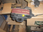
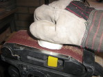
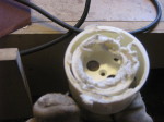
To save a bit of space and make everything fit better, I ended up cutting off the top of the outlets, so the outer mantle would come off and the outlets could be placed closer togeter. After doing the first one with a saw, I ended up doing all the others using a belt sander, fixed upside down in my vice creating an ad-hoc stationary belt sander.
Box construction
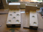
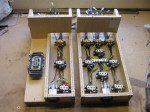
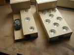
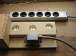
Next, I created a base for the boxes and constructed the boxes on top. Apparently I didn't take any pictures of the process (I remember doing so, but perhaps I somehow lost the pictures, not sure). The base plate is thick (18mm) MDF, on which I've used my router to route out a 10mm deep "trench" in the wood through which the cabling can be put (so it can go underneath the outlets). You can see one of the trenches on the left of the right box below.
Most of the rest of the construction is 15mm plywood, except for the top plate (with holes for the outlets), I used 6mm MDF for that.
Distribution wires
To connect the incoming power lines to each of the switches, I had a bit of a challenge. The switches have blade connectors, onto which blade receptacle connectors can be attached. These blade receptacles are "crimped" onto a cable. I tried to find some component that I could use to connect all a dozen of blade receptacles onto, but I couldn't find any of those. There are special blade connectors that allow daisy chaining each switch onto the next, but I didn't like the idea that the last switch would be connected through two dozen of crimp connections (and I did not have those daisy chaining connectors when I was working on this).
I also could not use a Twist-on wire connector, since that only works with solid cable (and the crimped blade connectors need stranded cable).
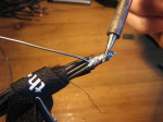
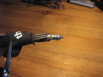
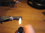
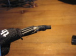
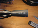
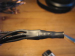
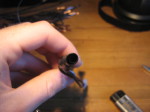
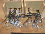
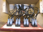
In the end, I just settled for soldering all these cables together. It's not very elegant, but I'm confident that this soldering connection should be capable of easily handling 16A of current, which is the most important in the end. I used two layers of heat-shrink tubing to insulate the big lump of soldering tin.
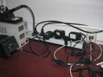
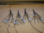
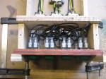
The last picture shows the end result: four cable octopusses that connect with one wire to the power entry point, and with eight wires to each of the switches. There's four of these in total, for both the line (with the brown marking tape) and neutral (with the white marking tape) connections in both of the boxes.
Connecting the outlets
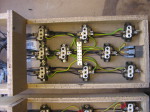
The line and neutral connections of each outlet need to be connected to a single switch. I first connected wires to all of the outlets, with a blade connector crimped onto the other side. I used wires cut from the multicable I bought, which are conveniently numbered. Since the line and neutral connections are interchangeable in the European outlet system ("Schuko"), I didn't need to add labels to distinguish both cables coming from the same outlet.
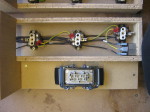
The earth terminals do not need to pass the switch, these need to be always connected. In the bigger box, I used an earthing terminal block (which is intended to be used in a breaker box) to connect the outlets in a "star" topology. For the smaller box, I couldn't find a smaller earthing terminal block, so I just daisy chained the outlets together. Since there's only a few outlets and there should never be much current through the earth terminals, this shouldn't be a problem here.
I also connected the multicable connector in the same way, but those wires are already covered by a MDF plate in the pictures.
The end result is 32 cables sticking out from each box, four cables for each switch.
Connecting the switches
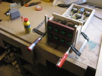
Connecting the switches was a matter of connecting all the 32 wires I prepared to the switches in the panel. After connecting the switches, I glued the front panel onto the box (so there would not be any visible screws on the front panel).
Assembled boxes
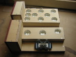
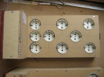
Now the boxes are assembled and ready for use, time to build the external outlet bar.
Note that the outlets seem a bit randomly placed, but I've tried to leave as much room available for power adapters to stick out in different directions, without blocking other outlets.
External outlets
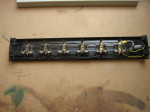
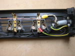
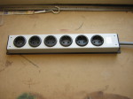
For the external outlets, I got an old powerbar (again at van Altena), which has each outlet individually connected internally. I connected the big multicable to all of the outlets on side and to the big connector on the other side of the cable
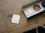
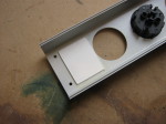
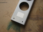
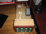
The old powerbar also had a single powerswitch to control all of the outlets. Since I couldn't find any use for this switch, I just removed it. To cover up the hole that it left, I used two rectangles cut out of an old plastic cable conduit. The smaller rectangle exactly fits in the hole, the larger rectangle just serves to glue the smaller one in place. The result is a cleanly covered switch hole.
Fixing the front panels
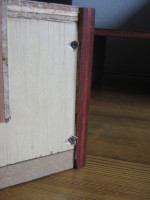
After installing the boxes into the cabinet, it turned out the front panels weren't glued on properly, the left one came off. Since I was already doubting if they would hold, I settled for a less elegant, but more secure solution: I just added some screws in an angle from the back, making them just long enough to not stick out at the front.
Finished
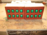
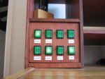
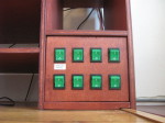
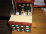
So, here's the finished thing. I really like the contrast between the green buttons and the red mahogany finish I used, it gives the thing a very classic look.
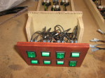
To be able to plug in devices, I can pull out the boxes towards the front. This is not very quick to do, but since I do not need to switch devices very often, that works out just fine.
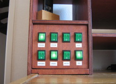
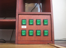
I also added labels to the various switches, so I won't have to remember where I plugged in every device.
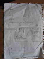
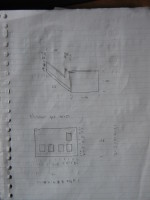
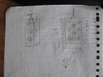
Design drawings
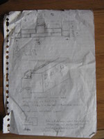
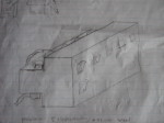
And just for historical reference, here are the design drawings I created during the process. If they look fuzzy to you, that's probably because I erased every part of the drawings probably at least once...


Comments are closed for this story.