
These are the ramblings of Matthijs Kooijman, concerning the software he hacks on, hobbies he has and occasionally his personal life.
Most content on this site is licensed under the WTFPL, version 2 (details).
Questions? Praise? Blame? Feel free to contact me.
My old blog (pre-2006) is also still available.
See also my Mastodon page.
| Sun | Mon | Tue | Wed | Thu | Fri | Sat |
|---|---|---|---|---|---|---|
| 1 | 2 | 3 | 4 | 5 | ||
| 6 | 7 | 8 | 9 | 10 | 11 | 12 |
| 13 | 14 | 15 | 16 | 17 | 18 | 19 |
| 20 | 21 | 22 | 23 | 24 | 25 | 26 |
| 27 | 28 | 29 | 30 | 31 |
(...), Arduino, AVR, BaRef, Blosxom, Book, Busy, C++, Charity, Debian, Electronics, Examination, Firefox, Flash, Framework, FreeBSD, Gnome, Hardware, Inter-Actief, IRC, JTAG, LARP, Layout, Linux, Madness, Mail, Math, MS-1013, Mutt, Nerd, Notebook, Optimization, Personal, Plugins, Protocol, QEMU, Random, Rant, Repair, S270, Sailing, Samba, Sanquin, Script, Sleep, Software, SSH, Study, Supermicro, Symbols, Tika, Travel, Trivia, USB, Windows, Work, X201, Xanthe, XBee
 &
&
(With plugins: config, extensionless, hide, tagging, Markdown, macros, breadcrumbs, calendar, directorybrowse, entries_index, feedback, flavourdir, include, interpolate_fancy, listplugins, menu, pagetype, preview, seemore, storynum, storytitle, writeback_recent, moreentries)
Valid XHTML 1.0 Strict & CSS
I mentioned earlier on that I had been given an old NES, without any accessories (no power adapter, no controllers, just the box itself). Having grand plans to use it for various cool mods, I needed to get it to work first. As I am writing this, Brenda is playing Mario bros on my NES, so it actually works!
Does it even work?
Using a bunch of borrowed (original NES) hardware, I established that both the NES and the Mario/duckhunt cartridge I had with it, were working. I did need to bend out the pins on the cartridge slot on the NES, but now it seems to make contact properly.
Last week, I bought a second hand NES controller, so I could start experimenting with it. This weekend, while I was in Enschede with Brenda, I have been toying around with it. I borrowed a power supply from Bert, which had conveniently and only supplied AC voltage (which is exactly what the NES wants, though DC should work as well). I connected the NES to the composite input of my workstation's TV card.
After remembering exactly how to properly setup my TV card (haven't been using it in years), I got a properly coloured and sized image. Only, the image was distorted here and there and sometimes sprites would disappear all together. The cause of this was the power supply: When the NES was turned on, it supplied only 6V instead of the 9V the NES required. The solution was to turn up the power supply to 12V, so it supplies about 8V when loaded (yes, the supply is a bit overloaded).
The only problem left so far, is a nasty low buzz in the audio. This is probably related to the unstable power supply, but is nasty nevertheless. I have tried filtering the signal to get the buzz out, but that failed because using my microphone input as an ALSA input just didn't work for some reason.
Anyway, I can now play Mario! Next project: Building my own zapper gun to play duck hunt!
I've been spending this evening for a just cause: Fixing our flat's toaster. It broke down somewhere around yesterday. At first, the toaster would not stay down and on, but later on the glowing wires wouldn't do their glowing act at all. Thinking I'd just have a quick look and repair the thing proved somewhat of a challenge...
Just this week, I've ordered a new toy: An Ergoriser. Or not really a toy actually, but a useful addition to my desktop. Last week I decided I wanted something like that, last monday (around midnight) I ordered it and wednesday it got delivered. Nice and quick.
Instead of fiddling around with cables to my external monitor or having to look down to my notebook while working, I can now put Xanthe (my notebook) up on my ergoriser, to get the screen on a decent and ergonomical height.
I still need to connect my keyboard and mouse to use them, though. I'd like to use bluetooth for that, but there is no bluetooth edition of my keyboard (or any other 'broken' ergonomical keyboard...) and I have not found any device that can connect USB peripherals through bluetooth.
So, I'm gonna be trying another option: Use Xdmx to put up a proxying xserver on Xanthe. Xdmx can dynamically attach and detach to other X servers, for graphical output as well as getting input. I'm not sure how exactly this will work out, though, but if everything works out, I will be able to use the CRT monitor on my desk through xdmx as well (it's connected to Katherina, my workstation).
To make it even fancyer, I should be able to attach the monitor and input devices automatically, through WLAN, as soon as I get home (using the wireless access point's MAC address to detect 'home'). Fun!
I've previously mentioned that I've undervolted my MSI Megabook S270 notebook. I got a request about how exactly I did this, so I'll elaborate here.
Background
Undervolting is modifying your hardware parameters in such a way, that the system CPU runs on a lower voltage that it is supposed to. Running on a lower voltage means the CPU uses less power and produces less heat, which are both wanted on a mobile system. Different laptops have different methods of undervolting. What I describe here should applies to AMD Turion64 processors (Which I have), but should also work for all other AMD processors with PowerNow support.
PowerNow & cpufreq
AMD PowerNow is AMD's technology for scaling CPU frequencies and voltages. How
exactly the scaling itself is performed is not all that interesting, how to
control it is. Linux has a special cpufreq driver for PowerNow processors,
which exports its interface through /sys/devices/system/cpu/cpu0/cpufreq.
Here you can select a governor which decides at what speed your CPU should
run.
Hidden from the cpufreq interface (which only concerns CPU speed changes), the PowerNow driver also changes the CPU voltage when the speed changes. So, your CPU voltage is already automatically decreased whenever the CPU speed is lowered. Yet, we want to decrease it even further.
ACPI
Since we cannot set the CPU voltage when scaling, only the frequency, how does PowerNow know what voltage to set? You might think that the CPU itself handles this, but fortunately this is not so. The PowerNow driver gets the information about the possible states and corresponding voltages from the system itself, through one of two means: ACPI and legacy BIOS.
The preferred way of retrieving this information is through ACPI and this
might or might not work. For me, this didn't work (There were errors in my
kernel logs with CONFIG_CPU_FREQ_DEBUG enabled). When ACPI does not work,
the PowerNow driver uses some legacy BIOS call I don't fully understand to get
its values.
So, we want to modify the voltage values the PowerNow driver finds. Since I didn't fully know how the BIOS thing worked, that wasn't the way to go. So I had two options:
- Hack/hardcode the voltage settings in my kernel
- Fix my ACPI and modify my ACPI table.
I settled for the last one, since that is nicer and a lot better when upgrading kernels.
Fixing ACPI
Some poking around with the kernel and its debug output, I found that the ACPI object (CPU1._PSS) holding the PowerNow information was not properly loaded by the kernel. Doing the decompile-and-recompile-with-Intel's-compiler trick, showed that the Intel ACPI compiler didn't like that _PSS ACPI object either. See my older post about how I fixed these compilation errors. After fixing these, the PowerNow driver properly gets its settings from ACPI.
With CONFIG_CPU_FREQ_DEBUG enabled, PowerNow properly reports the found
settings (don't know if this was any different before fixing ACPI, I don't
want to break my ACPI and reboot to find out).
powernow-k8: Found 1 AMD Athlon 64 / Opteron processors (version 1.50.4)
powernow-k8:    0 : fid 0x8, vid 0xa
powernow-k8:    1 : fid 0x0, vid 0x1c
powernow-k8:    0 : fid 0x8 (1600 MHz), vid 0xa (1300 mV)
powernow-k8:    1 : fid 0x0 (800 MHz), vid 0x16 (1000 mV)
powernow-k8: cpu0, init lo 0x808, hi 0x1
powernow-k8: policy current frequency 1600000 kHz
cpu_init done, current fid 0x8, vid 0x8
Part of fixing the ACPI table, is recompiling a fixed version and inserting it into the kernel source. Now, instead of getting the ACPI table from the system on startup, Linux uses your modified table. This means we can modify any value in the table as if the actual ACPI table was changed.
Tweaking PowerNow
Time to turn to find out how to read the ACPI table and find out which value to actually change. After searching a lot I found the "BIOS and kernel developers guide for Athlon 64 and Opteron". At page 278 they describe where PowerNow gets its information. From there I find that the CPU1._PSS ACPI Package contains a number of (unnamed) packages, one for every CPU State (Two in my case). Each packets contains 6 32bits numbers, which represent various settings. This is my original _PSS Package:
Name (_PSS, Package (0x02)
{
    Package (0x06)
    {
        0x00000640,
        0x000055F0,
        0x00000064,
        0x00000007,
        0xE0202A88,
        0x00000288
    },

    Package (0x06)
    {
        0x00000320,
        0x00001EDC,
        0x00000064,
        0x00000007,
        0xE0202D80,
        0x00000580
    }
})
From the PowerNow specs we learn that every CPU state has a fid and vid, for Frequency ID and Voltage ID respectively. The frequency is calculated as 800 + fid * 100 (in MHz). The voltage is calculated as 1550 - vid * 25 (in mV). This means the frequency cannot go below 800MHz, and since the maximum vid value is 0x1e the minimum voltage is 800mV. I seem to vaguely remember that either the fid or vid can only be set to multiples of 2, yet I can't seem to find any hint of that in the specs now. I did find that the maximum supported frequency change in one go is 200MHz, but the kernel takes care of that, so we don't need to worry about this.
The actual vid is coded into the fifth value in the package, at bits 6-10
(Powernow specs page 280). This means you can increment the fifth value
by 0x80 to decrease the voltage by 50mV. Below is the package from the ACPI
table I use now, along with a few other examples of different voltages (//
denotes a comment).
Package (0x06)
{
    0x00000320,
    0x00001EDC,
    0x00000064,
    0x00000007,
    //0xE0202D80, // 1000mV
    //0xE0202E80,  // 900 mV
    0xE0202F00,  // 850 mV
    //0xE0202F80,  // 800 mV
    0x00000580
}
I've tried running as low as 800mV, but then my system seems to boot okay, but as soon as I login (type my password correctly), it powers off. This seems so predictable that you would suspect the voltage change to have this effect, but increasing the voltage back to 850 mV gives me a stable system that is slightly cooler and uses less power. I'll repeat the (very rough) benchmarks I made back then here (current values are for the entire system).
- 800MHz, 800mV - Crash on startup
- 800MHz, 850mV - ~980mA/39°C idle, ~1170mA/48°C load
- 800MHz, 1000mV - ~1020mA/41°C idle, ~1330mA/50°C load
As you can see, the power savings are very little when the CPU is idle, but quite significant when the CPU gets busy (100% load, though still at 800MHz). I have so for only undervolted my 800MHz state, since I barely ever need all my 1600MHz. But since my CPU gets especially power hungry when it's really fully loaded at 1600MHz (up to 2500mA), I suspect that a lot of power can be saved here. If you try this and get it to work, do tell! And don't forget to mention the actual voltage you get it to run on.
Update: Youri Matthys has been experimenting with undervolting too, and has managed to make his Turion at 1600Mhz run on 1000mV instead of the default 1300mV. The power savings are even better then I'd have hoped for: Under full load the battery usage drops from around 2500mA to 1700mA.
Just a little heads up for anyone owning an Asus access point. I spent the day at Brenda's today and their access needed a firmware upgrade. After a first failed attempt (upgrading the access point over the wireless connection is a bad idea and crashed the web management interface, requiring a reboot) I managed to succesfully upgrade the access point.
Yet, even though the upgrade page claimed that "all settings will be preserved", after upgrading we had a brand new (unencrypted) wireless network in town, with an SSID of "Broadcom" (wasn't this an Asus device?). So much for saving our settings... But, not only did it throw away our wireless settings, also the administrator password went out the window. Better yet, apparently it was not replaced with the default "admin/admin" password, since that didn't work.
So, your effectively locked out of your own acces point. That's bad points for Asus there... But if you should find yourself in this same situation, don't panic! Just press the reset button on the back of your AP to restore it to factory default settings. Tada, it works again, and since it trashed your settings anyway, you don't lose anything :-)
I've been working on my own binary clock for a while now. I've managed to get the PIC microcontroller from Microchip working for some time now. After being busy with other stuff I slowly resurrected this project. Since the microcontroller part is mostly done (the software works, for the limited prototype hardware I have so far), I am focussing on the actual casing for the clock now.
Casing
The casing of the clock has a big influence on the rest of the hardware (and thus software) design. The basic idea of a binary clock is to have 3 rows of 6 LEDs each, one row for hours, minutes and seconds, each representing a binary number. Since representating a binary number isn't limited to leds but anything that can represent on and off, 1 and 0.
I'll settle for leds for now since they are easy to use and give pretty lights. The exact form is not decided yet. I had this idea of making the clock a very flat box, probably black, with 18 small (1cm) squares that illuminate (something like the TIX Pattern clock, but smaller). For that I would need white leds and colored, halftransparent plastic to put in the squares.
Shopping spree
So I went shopping today and returned with a bunch of stuff. I got some fully transparent and half transparent sturdy plastic from a hobby shop, I got some colored half transparent plastic from a carrying folder and a handful of leds in yellow, green, blue and white. I also returned with a toy gun (full metal, so nice and heavy!) for lextalionis perhaps, liquid latex that is hopefully fit for making LARP weapons and looking for a box of pins, a nice 1000 page book about hardware design of game consoles, but that's beside the point.
The box design
I also found a box meant to hold sewing accesoires. It is a half-transparent plastic that contains 18 compartments (or 17 really, since one panel is missing). When I saw it I got a vision of the backside of the box, every compartment being one bit of the clock, with leds inside.
It turned out this idea actually seemed to work out nicely. I haven't been able to try this with multiple compartments lighting up at the same time, I expect I need to add some extra (light) shielding between the compartments. Also, I need LEDs with a bigger angle. Since my leds focus the light in a tight angle, only a part of the compartment backside is lit. If I put the led within a compartement, only a small circle of light appears at the outside. I need to put the LED about 10cm from the backside to get full coverage, which is impractical and reduces light strength.
Though this design seems to be quite nice, there are two main disadvantages to it. First, when it is turned off, the clock will probably look butt ugly. After all, it's not more than a plastic bogs when the lights are off. Second, the box is big. It's way bigger than needed to hold the leds, wiring and other electronics. I would say somewhere between 95% and 99% of the space is unused. Not so nice.
I'll get some wider angle LEDS first and then I'll see if I'm gonna build it like this. For now the box serves as a way better storage for a bunch of resistors, leds and other electronic components than the small glass bowl that used to contain my electronic junk.
The squares design
As noted above, I was envisioning some sort of black box containing coloured squares that could light up. I tried this design using a few layers of paper (not black, but you didn't see the difference with the lights off) with a hole in them. I put a coloured piece of plastic with a white light behind it. This was not very succesful. The white light is so bright, you barely saw the blue colour of the plastic. When using uncoloured plastic, the light was just too bright to look in.
The other approach, using half-transparent uncoloured plastic squares, with coloured LEDs behind then, worked out better. The red, yellow and green leds had the advantage of being less bright (nicer to the eye). The blue led looked nice, but was still a little bright.
All leds suffered from the same problem as with the box design above: Their viewing angle is too small. I had to put the leds at a distance of around 5cm from the paper, which is way more that the thickness I had in mind. Also, due to this focussing the center of the square is brighter than the edges.
This looks like a very promising design. I need to get a decent piece of (black) wood, plastic or cardboard to do some more tests once I can get my hands on some wide angled LEDs.
Note to self: Get a cheap digital camera, since conveying these ideas in words is crappy ;-)
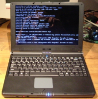
Anyway, about The notebook I ordered finally arrived a week and a half ago. I have been playing around with it during the last week, therefore I have not posted this earlier :-)
I rather like the notebook already. I have yet to name her, but she's cute, small, a little alternative (with an AMD processor instead of an Intel one) and gothic (Dressed in all black). It's a perfect fit in my backpack, but I still want to get one of those second skin notebook sleeves to protect the notebook from the other residents of my bag :-) I've ordered one at the the Mediamarkt, but I'm not sure if it will fit properly (My screen is 12" widescreen, which is a few cm wider than most 12" laptops).
Read on for specs, linux hardware support, ACPI tables & voltage optimization.