These are the ramblings of Matthijs Kooijman, concerning the software he hacks on, hobbies he has and occasionally his personal life.
Most content on this site is licensed under the WTFPL, version 2 (details).
Questions? Praise? Blame? Feel free to contact me.
My old blog (pre-2006) is also still available.
See also my Mastodon page.
| Sun | Mon | Tue | Wed | Thu | Fri | Sat |
|---|---|---|---|---|---|---|
| 1 | 2 | 3 | ||||
| 4 | 5 | 6 | 7 | 8 | 9 | 10 |
| 11 | 12 | 13 | 14 | 15 | 16 | 17 |
| 18 | 19 | 20 | 21 | 22 | 23 | 24 |
| 25 | 26 | 27 | 28 | 29 | 30 | 31 |
(...), Arduino, AVR, BaRef, Blosxom, Book, Busy, C++, Charity, Debian, Electronics, Examination, Firefox, Flash, Framework, FreeBSD, Gnome, Hardware, Inter-Actief, IRC, JTAG, LARP, Layout, Linux, Madness, Mail, Math, MS-1013, Mutt, Nerd, Notebook, Optimization, Personal, Plugins, Protocol, QEMU, Random, Rant, Repair, S270, Sailing, Samba, Sanquin, Script, Sleep, Software, SSH, Study, Supermicro, Symbols, Tika, Travel, Trivia, USB, Windows, Work, X201, Xanthe, XBee
 &
&
(With plugins: config, extensionless, hide, tagging, Markdown, macros, breadcrumbs, calendar, directorybrowse, entries_index, feedback, flavourdir, include, interpolate_fancy, listplugins, menu, moreentries, pagetype, preview, seemore, storynum, storytitle, writeback_recent)
Valid XHTML 1.0 Strict & CSS

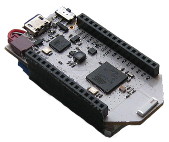
The Pinoccio Scout is a wonderful Arduino-like microcontroller board that has builtin mesh networking, a small form factor and a ton of resources (at least in Arduino terms: 32K of SRAM and 256K of flash).
However, flashing a new program into the scout happens through a serial port at 115200 baud. That's perfectly fine when you only have 32K of flash or for occasional uploads. But when you upload a 100k+ program dozens of times per day, it turns out that that's actually really slow! Uploading and verifying a 104KiB sketch takes over 30 seconds, just too long to actually wait for it (so you do something else, get distracted, and gone is the productivity).

Last week, I got a fancy new JTAGICE3 programmer / debugger. I wanted to achieve two things in my Pinoccio work: Faster uploading of programs (Having 256k of flash space is nice, but flashing so much code through a 115200 baud serial connection is slow...) and doing in-circuit debugging (stepping through code and dumping variables should turn out easier than adding serial prints and re-uploading every time).
In any case, the JTAGICE3 device is well-supported by avrdude, the
opensource uploader for AVR boards. However, unlike devices like the
STK500 development board, the AVR dragon programmer/debugger and the
Arduino bootloader, which use an (emulated) serial port to communicate,
the JTAGICE3 uses a native USB protocol. The upside is that the data
transfer rate is higher, but the downside is that the kernel doesn't
know how to talk to the device, so it doesn't expose something like
/dev/ttyUSB0 as for the other devices.
avrdude solves this by using libusb, which can talk to USB devices
directly, through files in /dev/usb/. However, by default these device
files are writable only by root, since the kernel has no idea what kind
of devices they are and whom to give permissions.
To solve this, we'll have to configure the udev daemon to create the
files in /dev/usb with the right permissions. I created a file called
/etc/udev/rules.d/99-local-jtagice3.rules, containg just this line:
SUBSYSTEM=="usb", ATTRS{idVendor}=="03eb", ATTRS{idProduct}=="2110", GROUP="dialout"
This matches the JTAGICE3 specifically using it's USB vidpid (03eb:2110,
use lsusb to find the id of a given device) and changes the group for
the device file to dialout (which is also used for serial devices on
Debian Linux), but you might want to use another group (don't forget to
add your own user to that group and log in again, in any case).
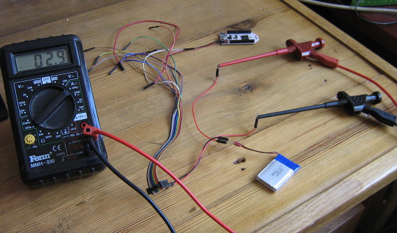
Recently, I needed to do battery current draw measurements on my Pinoccio boards. Since the battery is connected using this tinywiny JST connector, I couldn't just use some jumper wires to redirect the current flow through my multimeter. I ended up using jumper wires, combined with my Bus Pirate fanout cable, which has female connectors just small enough, to wire everything up. The result was a bit of a mess:

Admittedly, once I cleaned up all the other stuff around it from my desk for this picture, it was less messy than I thought, but still, jamming in jumper wires into battery connectors like this is bound to wear them out.
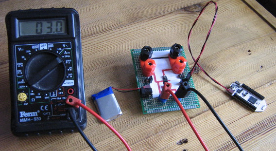
So, I ordered up some JST FSH connectors (as used by the battery) and some banana sockets and built a simple board that allows connecting a power source and a load, keeping the ground pins permanently connected, but feeding the positive pins through a pair of banana sockets where a current meter can plug in. For extra flexibility, I added a few other connections, like 2.54mm header pins and sockets, a barrel jack plug and more banana sockets for the power source and load. I just realized I should also add USB connectors, so I can easily measure current used by an USB device.
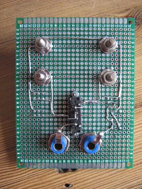
The board also features a switch (after digging in my stash, I found one old three-way switch, which is probably the first component to die in this setup. The switch allows switching between "on", "off" and "redirect through measurement pins" modes. I tried visualizing the behaviour of the pins on the top of the PCB, but I'm not too happy with the result. Oh well, as long as I know what does :-)
All I need is a pretty case to put under the PCB and a μCurrent to measure small currents accurately and I'm all set!
Update: The board was expanded by adding an USB-A and USB-B plug to interrupt USB power, with some twisted wire to keep the data lines connected, which seems to work (not shown in the image).

I recently got myself an Xprotolab Portable, which is essentially a tiny, portable 1Msps scope (in hindsight I might have better gotten the XMinilab Portable which is essentially the same, but slightly bigger, more expensive and with a bigger display. Given the size of the cables and carrying case, the extra size of the device itself is negligable, while the extra screen size is significant).
In any case, I wanted to update the firmware of the device, but the
instructions refer only to a Windows-only GUI utility from Atmel, called
"FLIP". I remembered seeing a flip.c file inside the avrdude sources
though, so I hoped I could also flash this device using avrdude on
Linux. And it worked! Turns out it's fairly simple.
- Activate the device's bootloader, by powering off, then press K1 and keep it pressed while turning the device back on with the menu key. The red led should light up, the screen will stay blank.
- Get the appropriate firmware hex files from the Xprotolab Portable page. You can find them at the "Hex" link in the top row of icons.
Run avrdude, for both the application and EEPROM contents:
sudo avrdude -c flip2 -p x32a4u -U application:w:xprotolab-p.hex:i
sudo avrdude -c flip2 -p x32a4u -U eep:w:xprotolab-p.eep:i
I'm running under sudo, since this needs raw USB access to the USB device. Alternatively, you can set up udev to offer access to your regular user (like I did for the JTAGICE3), but that's probably too much effort just for a one-off firmware update.
Done!
Note that you have to use avrdude version 6.1 or above, older versions don't support the FLIP protocol.


