These are the ramblings of Matthijs Kooijman, concerning the software he hacks on, hobbies he has and occasionally his personal life.
Most content on this site is licensed under the WTFPL, version 2 (details).
Questions? Praise? Blame? Feel free to contact me.
My old blog (pre-2006) is also still available.
See also my Mastodon page.
| Sun | Mon | Tue | Wed | Thu | Fri | Sat |
|---|---|---|---|---|---|---|
| 1 | 2 | 3 | ||||
| 4 | 5 | 6 | 7 | 8 | 9 | 10 |
| 11 | 12 | 13 | 14 | 15 | 16 | 17 |
| 18 | 19 | 20 | 21 | 22 | 23 | 24 |
| 25 | 26 | 27 | 28 | 29 | 30 | 31 |
(...), Arduino, AVR, BaRef, Blosxom, Book, Busy, C++, Charity, Debian, Electronics, Examination, Firefox, Flash, Framework, FreeBSD, Gnome, Hardware, Inter-Actief, IRC, JTAG, LARP, Layout, Linux, Madness, Mail, Math, MS-1013, Mutt, Nerd, Notebook, Optimization, Personal, Plugins, Protocol, QEMU, Random, Rant, Repair, S270, Sailing, Samba, Sanquin, Script, Sleep, Software, SSH, Study, Supermicro, Symbols, Tika, Travel, Trivia, USB, Windows, Work, X201, Xanthe, XBee
 &
&
(With plugins: config, extensionless, hide, tagging, Markdown, macros, breadcrumbs, calendar, directorybrowse, entries_index, feedback, flavourdir, include, interpolate_fancy, listplugins, menu, pagetype, preview, seemore, storynum, storytitle, writeback_recent, moreentries)
Valid XHTML 1.0 Strict & CSS
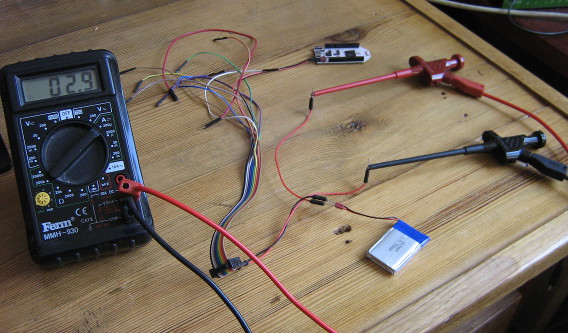
Recently, I needed to do battery current draw measurements on my Pinoccio boards. Since the battery is connected using this tinywiny JST connector, I couldn't just use some jumper wires to redirect the current flow through my multimeter. I ended up using jumper wires, combined with my Bus Pirate fanout cable, which has female connectors just small enough, to wire everything up. The result was a bit of a mess:

Admittedly, once I cleaned up all the other stuff around it from my desk for this picture, it was less messy than I thought, but still, jamming in jumper wires into battery connectors like this is bound to wear them out.
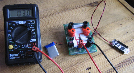
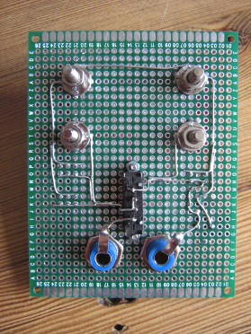
So, I ordered up some JST FSH connectors (as used by the battery) and some banana sockets and built a simple board that allows connecting a power source and a load, keeping the ground pins permanently connected, but feeding the positive pins through a pair of banana sockets where a current meter can plug in. For extra flexibility, I added a few other connections, like 2.54mm header pins and sockets, a barrel jack plug and more banana sockets for the power source and load. I just realized I should also add USB connectors, so I can easily measure current used by an USB device.
The board also features a switch (after digging in my stash, I found one old three-way switch, which is probably the first component to die in this setup. The switch allows switching between "on", "off" and "redirect through measurement pins" modes. I tried visualizing the behaviour of the pins on the top of the PCB, but I'm not too happy with the result. Oh well, as long as I know what does :-)
All I need is a pretty case to put under the PCB and a μCurrent to measure small currents accurately and I'm all set!
Update: The board was expanded by adding an USB-A and USB-B plug to interrupt USB power, with some twisted wire to keep the data lines connected, which seems to work (not shown in the image).


Comments are closed for this story.