These are the ramblings of Matthijs Kooijman, concerning the software he hacks on, hobbies he has and occasionally his personal life.
Most content on this site is licensed under the WTFPL, version 2 (details).
Questions? Praise? Blame? Feel free to contact me.
My old blog (pre-2006) is also still available.
See also my Mastodon page.
| Sun | Mon | Tue | Wed | Thu | Fri | Sat |
|---|---|---|---|---|---|---|
| 1 | 2 | 3 | ||||
| 4 | 5 | 6 | 7 | 8 | 9 | 10 |
| 11 | 12 | 13 | 14 | 15 | 16 | 17 |
| 18 | 19 | 20 | 21 | 22 | 23 | 24 |
| 25 | 26 | 27 | 28 | 29 | 30 | 31 |
(...), Arduino, AVR, BaRef, Blosxom, Book, Busy, C++, Charity, Debian, Electronics, Examination, Firefox, Flash, Framework, FreeBSD, Gnome, Hardware, Inter-Actief, IRC, JTAG, LARP, Layout, Linux, Madness, Mail, Math, MS-1013, Mutt, Nerd, Notebook, Optimization, Personal, Plugins, Protocol, QEMU, Random, Rant, Repair, S270, Sailing, Samba, Sanquin, Script, Sleep, Software, SSH, Study, Supermicro, Symbols, Tika, Travel, Trivia, USB, Windows, Work, X201, Xanthe, XBee
 &
&
(With plugins: config, extensionless, hide, tagging, Markdown, macros, breadcrumbs, calendar, directorybrowse, entries_index, feedback, flavourdir, include, interpolate_fancy, listplugins, menu, pagetype, preview, seemore, storynum, storytitle, writeback_recent, moreentries)
Valid XHTML 1.0 Strict & CSS
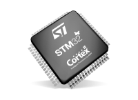
Recently, I've been working with STM32 chips for a few different projects and customers. These chips are quite flexible in their pin assignments, usually most peripherals (i.e. an SPI or UART block) can be mapped onto two or often even more pins. This gives great flexibility (both during board design for single-purpose boards and later for a more general purpose board), but also makes it harder to decide and document the pinout of a design.
ST offers STM32CubeMX, a software tool that helps designing around an STM32 MCU, including deciding on pinouts, and generating relevant code for the system as well. It is probably a powerful tool, but it is a bit heavy to install and AFAICS does not really support general purpose boards (where you would choose between different supported pinouts at runtime or compiletime) well.
So in the past, I've used a trusted tool to support this process: A spreadsheet that lists all pins and all their supported functions, where you can easily annotate each pin with all the data you want and use colors and formatting to mark functions as needed to create some structure in the complexity.
However, generating such a pinout spreadsheet wasn't particularly easy. The tables from the datasheet cannot be easily copy-pasted (and the datasheet has the alternate and additional functions in two separate tables), and the STM32CubeMX software can only seem to export a pinout table with alternate functions, not additional functions. So we previously ended up using the CubeMX-generated table and then adding the additional functions manually, which is annoying and error-prone.
So I dug around in the CubeMX data files a bit, and found that it has an XML file for each STM32 chip that lists all pins with all their functions (both alternate and additional). So I wrote a quick Python script that parses such an XML file and generates a CSV script. The script just needs Python3 and has no additional dependencies.
To run this script, you will need the XML file for the MCU you are interested in from inside the CubeMX installation. Currently, these only seem to be distributed by ST as part of CubeMX. I did find one third-party github repo with the same data, but that wasn't updated in nearly two years). However, once you generate the pin listing and publish it (e.g. in a spreadsheet), others can of course work with it without needing CubeMX or this script anymore.
For example, you can run this script as follows:
$ ./stm32pinout.py /usr/local/cubemx/db/mcu/STM32F103CBUx.xml
name,pin,type
VBAT,1,Power
PC13-TAMPER-RTC,2,I/O,GPIO,EXTI,EVENTOUT,RTC_OUT,RTC_TAMPER
PC14-OSC32_IN,3,I/O,GPIO,EXTI,EVENTOUT,RCC_OSC32_IN
PC15-OSC32_OUT,4,I/O,GPIO,EXTI,ADC1_EXTI15,ADC2_EXTI15,EVENTOUT,RCC_OSC32_OUT
PD0-OSC_IN,5,I/O,GPIO,EXTI,RCC_OSC_IN
(... more output truncated ...)
The script is not perfect yet (it does not tell you which functions correspond to which AF numbers and the ordering of functions could be improved, see TODO comments in the code), but it gets the basic job done well.
You can find the script in my "scripts" repository on github.
Update: It seems the XML files are now also available separately on github: https://github.com/STMicroelectronics/STM32_open_pin_data, and some of the TODOs in my script might be solvable.
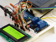
For a customer, I've been looking at RS-485 and MODBUS, two related protocols for transmitting data over longer distances, and the various Arduino libraries that exist to work with them.
They have been working on a project consisting of multiple Arduino boards that have to talk to each other to synchronize their state. Until now, they have been using I²C, but found that this protocol is quite susceptible to noise when used over longer distances (1-2m here). Combined with some limitations in the AVR hardware and a lack of error handling in the Arduino library that can cause the software to lock up in the face of noise (see also this issue report), makes I²C a bad choice in such environments.
So, I needed something more reliable. This should be a solved problem, right?
For a theatre performance, I needed to make the tail lights of an old car controllable through the DMX protocol, which the most used protocol used to control stage lighting. Since these are just small incandescent lightbulbs running on 12V, I essentially needed a DMX-controllable 12V dimmer. I knew that there existed ready-made modules for this to control LED-strips, which also run at 12V, so I went ahead and tried using one of those for my tail lights instead.
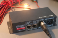
I looked around ebay for a module to use, and found this one. It seems the same design is available from dozens of different vendors on ebay, so that's probably clones, or a single manufacturer supplying each.
DMX module details
This module has a DMX input and output using XLR or a modular connector, and screw terminals for 12V power input, 4 output channels and one common connection. The common connection is 12V, so the output channels sink current (e.g. "Common anode"), which is relevant for LEDs. For incandescent bulbs, current can flow either way, so this does not really matter.
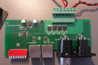
Opening up the module, it seems fairly simple. There's a microcontroller (or dedicated DMX decoder chip? I couldn't find a datasheet) inside, along with two RS-422 transceivers for DMX, four AP60T03GH MOSFETS for driving the channels, and one linear regulator to generate a logic supply voltage.
On the DMX side, this means that the module has a separate input and output signals (instead of just connecting them together). It also means that the DMX signal is not isolated, which violates the recommendations of the DMX specification AFAIU (and might be problematic if there is more than a few volts of ground difference). On the output side, it seems there are just MOSFETs to toggle the output, without any additional protection.
XBee modules are a range of wireless modules built by Digi, and are typically used to add wireless connectivity to Arduino or other microcontroller based projects. To configure these modules and update their firmware, you can use the XCTU configuration utility. This utility uses a serial port to talk to the XBee module, so you will need some way to connect to the XBee module to a serial port on your computer (using a USB "TTL" serial port, a "real" RS232 port has too high voltage).
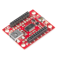
The easiest way is to use a dedicated board, like the SparkFun Explorer USB:
However, if you already have an Arduino and an XBee shield for it, you might want to use those to connect XCTU to your XBee module. In theory, this should be a matter of re-arranging some wires, but in practice I've run into some problems attempting this (depending on the hardware used).
In this post, I'll show a few ways to do this using an Arduino and a shield, and explain some of the problems you might run into.

My book about Arduino and XBee includes a chapter on battery power and sleeping. When I originally wrote it, it ended up over twice the number of pages originally planned for it, so I had to severely cut down the content. Among the content removed, was a large section talking about interrupts, sleeping and race conditions. Since I am not aware of any other online sources that cover this subject as thoroughly, I decided to publish this content as a blogpost separately, which is what you're looking at now.
In this blogpost, I will first explain interrupts and race conditions using a number of examples. Then sleeping is added into the mix, which again results in some interesting race conditions. All these examples have been written for Arduino boards using the AVR architecture, but the general concepts apply equally well to other platforms.
The basics of interrupts and sleeping on AVR are not covered in detail here. If you have no experience with this, I recommend these excellent articles on interrupts and on sleeping by Nick Gammon, which cover interrupts, sleeping and other powersaving in a lot of detail.
Yay! Last night (yes really night, it was 4:30 AM) I finalized and submitted the last chapter of my book. There's still a few details left, but the text of the book is out of my hands now, and the great folks at Packt publishing are now doing their magic with correcting my English, testing my code, layouting the book, and so on.
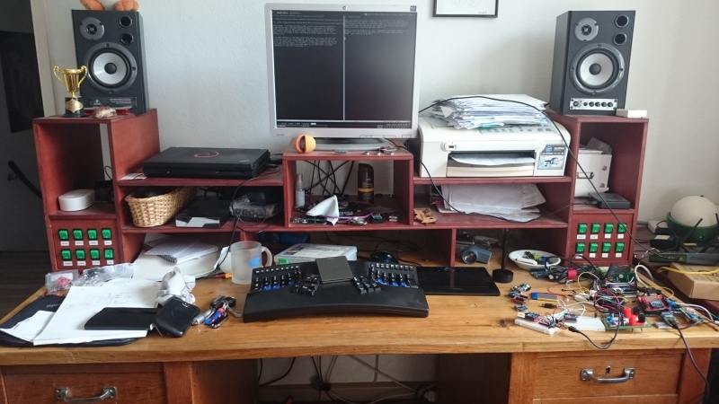
Great to have the pressure of these (repeatedly postponed) deadlines off my back, so I can finally take some time to do some long-due other stuff. Like cleaning up my desk:
Past summer, I've been writing a book, which is now nearing completion. A few months ago I was approached by Packt, a publisher of technical books, which want to add a book about sensor networks using Arduino and XBee modules to their lineup, and asked me to write it. The result will be a book titled "Building Wireless Sensor Networks Using Arduino".
I've been working on the book since then and am now busy with the last revisions on the text and examples. Turns out that writing a book is a lot more work than I had anticipated, though that might be partly due to my own perfectionism. In any case, I'll be happy when I'm done in a few weeks and can spend some time again on all the stuff I've been postponing in the last few months :-)
Last year, I got myself an Atmel JTAGICE3 programmer, in order to speed up programming my Pinoccio boards. This worked great, except that as can be expected of the tiny flatcable they used (1.27mm connector and even smaller flatcable), the cable broke within 6 months.
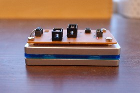
Atmel support didn't want to replace it, because it wasn't broken when I first unpacked the programmer, and told me to find and buy a new cable myself. Since finding these cables turns out to be tricky, and I didn't feel like breaking another cable in 6 months, I designed a converter board.

When working with an Arduino, you often want the serial console to stay open, for debugging. However, while you have the serial console open, uploading will not work (because the upload relies on the DTR pin going from high to low, which happens when opening up the serial port, but not if it's already open). The official IDE includes a serial console, which automatically closes when you start an upload (and once this pullrequest is merged, automatically reopens it again).
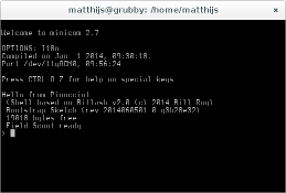
However, of course I'm not using the GUI serial console in the IDE, but minicom, a text-only serial console I can run inside my screen. Since the IDE (which I do use for compiling uploading, by calling it on the commandline using a Makefile - I still use vim for editing) does not know about my running minicom, uploading breaks.
I fixed this using some clever shell scripting and signal-passing. I
have an arduinoconsole script (that you can pass the port number to
open - pass 0 for /dev/ttyACM0) that opens up the serial console, and
when the console terminates, it is restarted when you press enter, or a
proper signal is received.
The other side of this is the Makefile I'm using, which kills the serial console before uploading and sends the restart signal after uploading. This means that usually the serial console is already open again before I switch to it (or, I can switch to it while still uploading and I'll know uploading is done because my serial console opens again).
For convenience, I pushed my scripts to a github repository, which makes it easy to keep them up-to-date too:
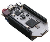
The Pinoccio Scout is a wonderful Arduino-like microcontroller board that has builtin mesh networking, a small form factor and a ton of resources (at least in Arduino terms: 32K of SRAM and 256K of flash).
However, flashing a new program into the scout happens through a serial port at 115200 baud. That's perfectly fine when you only have 32K of flash or for occasional uploads. But when you upload a 100k+ program dozens of times per day, it turns out that that's actually really slow! Uploading and verifying a 104KiB sketch takes over 30 seconds, just too long to actually wait for it (so you do something else, get distracted, and gone is the productivity).

