These are the ramblings of Matthijs Kooijman, concerning the software he hacks on, hobbies he has and occasionally his personal life.
Most content on this site is licensed under the WTFPL, version 2 (details).
Questions? Praise? Blame? Feel free to contact me.
My old blog (pre-2006) is also still available.
See also my Mastodon page.
| Sun | Mon | Tue | Wed | Thu | Fri | Sat |
|---|---|---|---|---|---|---|
| 1 | 2 | 3 | ||||
| 4 | 5 | 6 | 7 | 8 | 9 | 10 |
| 11 | 12 | 13 | 14 | 15 | 16 | 17 |
| 18 | 19 | 20 | 21 | 22 | 23 | 24 |
| 25 | 26 | 27 | 28 | 29 | 30 | 31 |
(...), Arduino, AVR, BaRef, Blosxom, Book, Busy, C++, Charity, Debian, Electronics, Examination, Firefox, Flash, Framework, FreeBSD, Gnome, Hardware, Inter-Actief, IRC, JTAG, LARP, Layout, Linux, Madness, Mail, Math, MS-1013, Mutt, Nerd, Notebook, Optimization, Personal, Plugins, Protocol, QEMU, Random, Rant, Repair, S270, Sailing, Samba, Sanquin, Script, Sleep, Software, SSH, Study, Supermicro, Symbols, Tika, Travel, Trivia, USB, Windows, Work, X201, Xanthe, XBee
 &
&
(With plugins: config, extensionless, hide, tagging, Markdown, macros, breadcrumbs, calendar, directorybrowse, entries_index, feedback, flavourdir, include, interpolate_fancy, listplugins, menu, moreentries, pagetype, preview, seemore, storynum, storytitle, writeback_recent)
Valid XHTML 1.0 Strict & CSS
For a theatre performance, I needed to make the tail lights of an old car controllable through the DMX protocol, which the most used protocol used to control stage lighting. Since these are just small incandescent lightbulbs running on 12V, I essentially needed a DMX-controllable 12V dimmer. I knew that there existed ready-made modules for this to control LED-strips, which also run at 12V, so I went ahead and tried using one of those for my tail lights instead.
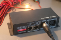
I looked around ebay for a module to use, and found this one. It seems the same design is available from dozens of different vendors on ebay, so that's probably clones, or a single manufacturer supplying each.
DMX module details
This module has a DMX input and output using XLR or a modular connector, and screw terminals for 12V power input, 4 output channels and one common connection. The common connection is 12V, so the output channels sink current (e.g. "Common anode"), which is relevant for LEDs. For incandescent bulbs, current can flow either way, so this does not really matter.
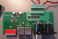
Opening up the module, it seems fairly simple. There's a microcontroller (or dedicated DMX decoder chip? I couldn't find a datasheet) inside, along with two RS-422 transceivers for DMX, four AP60T03GH MOSFETS for driving the channels, and one linear regulator to generate a logic supply voltage.
On the DMX side, this means that the module has a separate input and output signals (instead of just connecting them together). It also means that the DMX signal is not isolated, which violates the recommendations of the DMX specification AFAIU (and might be problematic if there is more than a few volts of ground difference). On the output side, it seems there are just MOSFETs to toggle the output, without any additional protection.


