These are the ramblings of Matthijs Kooijman, concerning the software he hacks on, hobbies he has and occasionally his personal life.
Most content on this site is licensed under the WTFPL, version 2 (details).
Questions? Praise? Blame? Feel free to contact me.
My old blog (pre-2006) is also still available.
See also my Mastodon page.
- Raspberry pi powerdown and powerup button (45)
- Repurposing the "Ecobutton" to skip spotify songs using Linux udev/hwdb key remapping (3)
- How to resize a cached LVM volume (with less work) (2)
- Reliable long-distance Arduino communication: RS485 & MODBUS? (6)
- USB, Thunderbolt, Displayport & docks (21)
| Sun | Mon | Tue | Wed | Thu | Fri | Sat |
|---|---|---|---|---|---|---|
| 1 | 2 | 3 | 4 | 5 | 6 | |
| 7 | 8 | 9 | 10 | 11 | 12 | 13 |
| 14 | 15 | 16 | 17 | 18 | 19 | 20 |
| 21 | 22 | 23 | 24 | 25 | 26 | 27 |
| 28 | 29 | 30 |
(...), Arduino, AVR, BaRef, Blosxom, Book, Busy, C++, Charity, Debian, Electronics, Examination, Firefox, Flash, Framework, FreeBSD, Gnome, Hardware, Inter-Actief, IRC, JTAG, LARP, Layout, Linux, Madness, Mail, Math, MS-1013, Mutt, Nerd, Notebook, Optimization, Personal, Plugins, Protocol, QEMU, Random, Rant, Repair, S270, Sailing, Samba, Sanquin, Script, Sleep, Software, SSH, Study, Supermicro, Symbols, Tika, Travel, Trivia, USB, Windows, Work, X201, Xanthe, XBee
 &
&
(With plugins: config, extensionless, hide, tagging, Markdown, macros, breadcrumbs, calendar, directorybrowse, feedback, flavourdir, include, interpolate_fancy, listplugins, menu, pagetype, preview, seemore, storynum, storytitle, writeback_recent, moreentries)
Valid XHTML 1.0 Strict & CSS
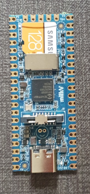
For a project (building a low-power LoRaWAN gateway to be solar powered) I am looking at simple and low-power linux boards. One board that I came across is the Milk-V Duo, which looks very promising. I have been playing around with it for just a few hours, and I like the board (and its SoC) very much already - for its size, price and open approach to documentation.
The board itself is a small (21x51mm) board in Raspberry Pi Pico form factor. It is very simple - essentially only a SoC and regulators. The SoC is the CV1800B by Sophgo, (a vendor I had never heard of until now, seems they were called CVITEK before). It is based on the RISC-V architecture, which is nice. It contains two RISC-V cores (one at 1Ghz and one at 700Mhz), as well as a small 8051 core for low-level tasks. The SoC has 64MB of integrated RAM.
The SoC supports the usual things - SPI, I²C, UART. There is also a CSI (camera) connector and some AI accelaration block, it seems the chip is targeted at the AI computer vision market (but I am ignoring that for my usecase). The SoC also has an ethernet controller and PHY integrated (but no ethernet connector, so you still need an external magjack to use it). My board has an SD card slot for booting, the specs suggest that there might also be a version that has on-board NAND flash instead of SD (cannot combine both, since they use the same pins).
There are two other variants - the Duo 256M with more RAM (board is identical except for 1 extra power supply, just uses a different SoC with more RAM) and the Duo S (in what looks like Rock Pi S form factor) which adds an ethernet and USB host port. I have not tested either of these and they use a different SoC series (SG200x) of the same chip vendor, so things I write might or might not be applicable to them (but the chips might actually be very similar internally, the CVx to SGx change seems to be related to the company merger, not necessarily technical differences).
The biggest (or at least most distinguishing) selling point, to me, is that both the chip and board manufacturers seem to be going for a very open approach. In particular:

After I recently ordered a new laptop, I have been looking for a USB-C-connected dock to be used with my new laptop. This turned out to be quite complex, given there are really a lot of different bits of technology that can be involved, with various (continuously changing, yes I'm looking at you, USB!) marketing names to further confuse things.
As I'm prone to do, rather than just picking something and seeing if it works, I dug in to figure out how things really work and interact. I learned a ton of stuff in a short time, so I really needed to write this stuff down, both for my own sanity and future self, as well as for others to benefit.
I originally posted my notes on the Framework community forum, but it seemed more appropriate to publish them on my own blog eventually (also because there's no 32,000 character limit here :-p).
There are still quite a few assumptions or unknowns below, so if you have any confirmations, corrections or additions, please let me know in a reply (either here, or in the Framework community forum topic).
Parts of this post are based on info and suggestions provided by others on the Framework community forum, so many thanks to them!
Getting started
First off, I can recommend this article with a bit of overview and history of the involved USB and Thunderbolt technolgies.
Then, if you're looking for a dock, like I was, the Framework community forum has a good list of docks (focused on Framework operability), and Dan S. Charlton published an overview of Thunderbolt 4 docks and an overview of USB-C DP-altmode docks (both posts with important specs summarized, and occasional updates too).
Then, into the details...
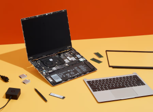
For a while, I've been considering replacing Grubby, my trusty workhorse laptop, a Thinkpad X201 that I've been using for the past 11 years. These thinkpads are known to last, and indeed mine still worked nicely, but over the years lost Bluetooth functionality, speaker output, one of its USB ports (I literally lost part of the connector), some small bits of the casing (dropped something heavy on it), the fan sometimes made a grinding noise, and it was getting a little slow at times (but still fine for work). I had been postponing getting a replacement, though, since having to figure out what to get, comparing models, reading reviews is always a hassle (especially for me...).
Then, when I first saw the Framework laptop last year, I was immediately sold. It's a laptop that aims to be modular, in the sense that it can be easily repaired and upgraded. To be honest, this did not seem all that special to me at first, but apparently in the 11 years since I last bought a laptop, manufacturers have been more using glue rather than screws, and solder rather than sockets, which is a trend that Framework hopes to turn.
In addition to the modularity, I like the fact they make repairability and upgradability an explicit goal, in attempt to make the electronics ecosystem more sustainable (they remind me of Fairphone in that sense). On top of that, it seems that this is also a really well made laptop, with a lot of attention to details, explicit support for Linux, open-source where possible (e.g. code for the embedded controller is open, ), flexible expansion ports using replacable modules, encouraging third parties to build and market their own expansion cards and addons (with open-source reference designs available), a mainboard that can be used standalone too (makes for a nice SBC after a mainboard upgrade), decent keyboard, etc.
The only things that I'm less enthusiastic about are the reflective screen (I had that on my previous laptop and I remember liking the switch to a matte screen, but I guess I'll get used to that), having just four expansion ports (the only fixed port is an audio jack, everything else - USB, displays, card reader - has to go through expansion modules, so we'll see if I can get by with four ports) and the lack of an ethernet port (apparently there is an ethernet expansion module in the works, but I'll probably have to get a USB-to-ethernet module in the meanwhile).
Unfortunately, when I found the Framework laptop a few months ago, they were not actually being sold yet, though they expected to open up pre-orders in December. I really hoped Grubby would last long enough so I could get a Framework laptop. Then pre-orders opened only for US and Canada, with shipping to the EU announced for Q1 this year. Then they opened up orders for Germany, France and the UK, and I still had to wait...
So when they opened up pre-orders in the Netherlands last month, I immediately placed my order. They are using a batched shipping system and my batch is supposed to ship "in March" (part of the batch has already been shipped), so I'm hoping to get the new laptop somewhere it the coming weeks.
I suspect that Grubby took notice, because last friday, with a small sputter, he powered off unexpectedly and has refused to power back on. I've tried some CPR, but no luck so far, so I'm afraid it's the end for Grubby. I'm happy that I already got my Framework order in, since now I just borrowed another laptop as a temporary solution rather than having to panic and buy something else instead.
So, I'm eager for my Framework laptop to be delivered. Now, I just need to pick a new name, and figure out which Thunderbolt dock I want... (I had an old-skool docking station for my Thinkpad, which worked great, but with USB-C and Thunderbolt's single cable for power, display, usb and ethernet, there is now a lot more choice in docks, but more on that in my next post...).
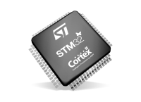
Recently, I've been working with STM32 chips for a few different projects and customers. These chips are quite flexible in their pin assignments, usually most peripherals (i.e. an SPI or UART block) can be mapped onto two or often even more pins. This gives great flexibility (both during board design for single-purpose boards and later for a more general purpose board), but also makes it harder to decide and document the pinout of a design.
ST offers STM32CubeMX, a software tool that helps designing around an STM32 MCU, including deciding on pinouts, and generating relevant code for the system as well. It is probably a powerful tool, but it is a bit heavy to install and AFAICS does not really support general purpose boards (where you would choose between different supported pinouts at runtime or compiletime) well.
So in the past, I've used a trusted tool to support this process: A spreadsheet that lists all pins and all their supported functions, where you can easily annotate each pin with all the data you want and use colors and formatting to mark functions as needed to create some structure in the complexity.
However, generating such a pinout spreadsheet wasn't particularly easy. The tables from the datasheet cannot be easily copy-pasted (and the datasheet has the alternate and additional functions in two separate tables), and the STM32CubeMX software can only seem to export a pinout table with alternate functions, not additional functions. So we previously ended up using the CubeMX-generated table and then adding the additional functions manually, which is annoying and error-prone.
So I dug around in the CubeMX data files a bit, and found that it has an XML file for each STM32 chip that lists all pins with all their functions (both alternate and additional). So I wrote a quick Python script that parses such an XML file and generates a CSV script. The script just needs Python3 and has no additional dependencies.
To run this script, you will need the XML file for the MCU you are interested in from inside the CubeMX installation. Currently, these only seem to be distributed by ST as part of CubeMX. I did find one third-party github repo with the same data, but that wasn't updated in nearly two years). However, once you generate the pin listing and publish it (e.g. in a spreadsheet), others can of course work with it without needing CubeMX or this script anymore.
For example, you can run this script as follows:
$ ./stm32pinout.py /usr/local/cubemx/db/mcu/STM32F103CBUx.xml
name,pin,type
VBAT,1,Power
PC13-TAMPER-RTC,2,I/O,GPIO,EXTI,EVENTOUT,RTC_OUT,RTC_TAMPER
PC14-OSC32_IN,3,I/O,GPIO,EXTI,EVENTOUT,RCC_OSC32_IN
PC15-OSC32_OUT,4,I/O,GPIO,EXTI,ADC1_EXTI15,ADC2_EXTI15,EVENTOUT,RCC_OSC32_OUT
PD0-OSC_IN,5,I/O,GPIO,EXTI,RCC_OSC_IN
(... more output truncated ...)
The script is not perfect yet (it does not tell you which functions correspond to which AF numbers and the ordering of functions could be improved, see TODO comments in the code), but it gets the basic job done well.
You can find the script in my "scripts" repository on github.
Update: It seems the XML files are now also available separately on github: https://github.com/STMicroelectronics/STM32_open_pin_data, and some of the TODOs in my script might be solvable.
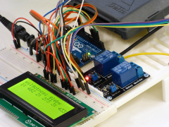
For a customer, I've been looking at RS-485 and MODBUS, two related protocols for transmitting data over longer distances, and the various Arduino libraries that exist to work with them.
They have been working on a project consisting of multiple Arduino boards that have to talk to each other to synchronize their state. Until now, they have been using I²C, but found that this protocol is quite susceptible to noise when used over longer distances (1-2m here). Combined with some limitations in the AVR hardware and a lack of error handling in the Arduino library that can cause the software to lock up in the face of noise (see also this issue report), makes I²C a bad choice in such environments.
So, I needed something more reliable. This should be a solved problem, right?
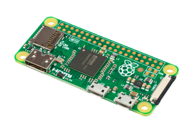
TL;DR: This post describes an easy way to add a power button to a raspberryp pi that:
- Only needs a button and wires, no other hardware components.
- Allows graceful shutdown and powerup.
- Only needs modification of config files and does not need a dedicated daemon to read GPIO pins.
There are two caveats:
- This shuts down in the same way as
shutdown -h noworhaltdoes. It does not completely cut the power (like some hardware add-ons do). - To allow powerup, the I²C SCL pin (aka GPIO3) must be used, conflicting with externally added I²C devices.
If you use Raspbian stretch 2017.08.16 or newer, all that is required is
to add a line to /boot/config.txt:
dtoverlay=gpio-shutdown,gpio_pin=3
Make sure to reboot after adding this line. If you need to use a
different gpio, or different settings, lookup gpio-shutdown in the
docs.
Then, if you connect a pushbutton between GPIO3 and GND (pin 5 and 6 on the 40-pin header), you can let your raspberry shutdown and startup using this button.
If you use an original Pi 1 B (non-plus) revision 1.0 (without mounting
holes), pin 5 will be GPIO1 instead of GPIO3 and you will need to
specify gpio_pin=1 instead. The newer revision 2.0 (with 2 mounting
holes in the board) and all other rpi models do have GPIO3 and work as
above.
All this was tested on a Rpi Zero W, Rpi B (rev 1.0 and 2.0) and a Rpi B+.
If you have an older Raspbian version, or want to know how this works, read on below.
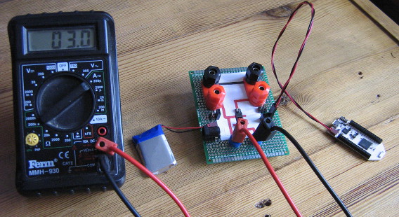
Recently, I needed to do battery current draw measurements on my Pinoccio boards. Since the battery is connected using this tinywiny JST connector, I couldn't just use some jumper wires to redirect the current flow through my multimeter. I ended up using jumper wires, combined with my Bus Pirate fanout cable, which has female connectors just small enough, to wire everything up. The result was a bit of a mess:
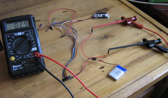
Admittedly, once I cleaned up all the other stuff around it from my desk for this picture, it was less messy than I thought, but still, jamming in jumper wires into battery connectors like this is bound to wear them out.
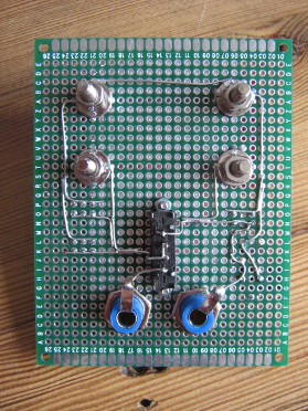
So, I ordered up some JST FSH connectors (as used by the battery) and some banana sockets and built a simple board that allows connecting a power source and a load, keeping the ground pins permanently connected, but feeding the positive pins through a pair of banana sockets where a current meter can plug in. For extra flexibility, I added a few other connections, like 2.54mm header pins and sockets, a barrel jack plug and more banana sockets for the power source and load. I just realized I should also add USB connectors, so I can easily measure current used by an USB device.
The board also features a switch (after digging in my stash, I found one old three-way switch, which is probably the first component to die in this setup. The switch allows switching between "on", "off" and "redirect through measurement pins" modes. I tried visualizing the behaviour of the pins on the top of the PCB, but I'm not too happy with the result. Oh well, as long as I know what does :-)
All I need is a pretty case to put under the PCB and a μCurrent to measure small currents accurately and I'm all set!
Update: The board was expanded by adding an USB-A and USB-B plug to interrupt USB power, with some twisted wire to keep the data lines connected, which seems to work (not shown in the image).
For a theatre performance, I needed to make the tail lights of an old car controllable through the DMX protocol, which the most used protocol used to control stage lighting. Since these are just small incandescent lightbulbs running on 12V, I essentially needed a DMX-controllable 12V dimmer. I knew that there existed ready-made modules for this to control LED-strips, which also run at 12V, so I went ahead and tried using one of those for my tail lights instead.
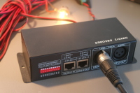
I looked around ebay for a module to use, and found this one. It seems the same design is available from dozens of different vendors on ebay, so that's probably clones, or a single manufacturer supplying each.
DMX module details
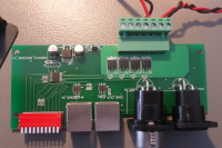
This module has a DMX input and output using XLR or a modular connector, and screw terminals for 12V power input, 4 output channels and one common connection. The common connection is 12V, so the output channels sink current (e.g. "Common anode"), which is relevant for LEDs. For incandescent bulbs, current can flow either way, so this does not really matter.
Opening up the module, it seems fairly simple. There's a microcontroller (or dedicated DMX decoder chip? I couldn't find a datasheet) inside, along with two RS-422 transceivers for DMX, four AP60T03GH MOSFETS for driving the channels, and one linear regulator to generate a logic supply voltage.
On the DMX side, this means that the module has a separate input and output signals (instead of just connecting them together). It also means that the DMX signal is not isolated, which violates the recommendations of the DMX specification AFAIU (and might be problematic if there is more than a few volts of ground difference). On the output side, it seems there are just MOSFETs to toggle the output, without any additional protection.
XBee modules are a range of wireless modules built by Digi, and are typically used to add wireless connectivity to Arduino or other microcontroller based projects. To configure these modules and update their firmware, you can use the XCTU configuration utility. This utility uses a serial port to talk to the XBee module, so you will need some way to connect to the XBee module to a serial port on your computer (using a USB "TTL" serial port, a "real" RS232 port has too high voltage).
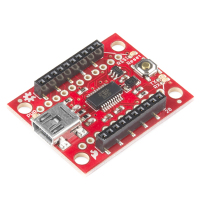
The easiest way is to use a dedicated board, like the SparkFun Explorer USB:
However, if you already have an Arduino and an XBee shield for it, you might want to use those to connect XCTU to your XBee module. In theory, this should be a matter of re-arranging some wires, but in practice I've run into some problems attempting this (depending on the hardware used).
In this post, I'll show a few ways to do this using an Arduino and a shield, and explain some of the problems you might run into.

My book about Arduino and XBee includes a chapter on battery power and sleeping. When I originally wrote it, it ended up over twice the number of pages originally planned for it, so I had to severely cut down the content. Among the content removed, was a large section talking about interrupts, sleeping and race conditions. Since I am not aware of any other online sources that cover this subject as thoroughly, I decided to publish this content as a blogpost separately, which is what you're looking at now.
In this blogpost, I will first explain interrupts and race conditions using a number of examples. Then sleeping is added into the mix, which again results in some interesting race conditions. All these examples have been written for Arduino boards using the AVR architecture, but the general concepts apply equally well to other platforms.
The basics of interrupts and sleeping on AVR are not covered in detail here. If you have no experience with this, I recommend these excellent articles on interrupts and on sleeping by Nick Gammon, which cover interrupts, sleeping and other powersaving in a lot of detail.

